


6-22 Programming MN792
Digital Inputs Continued
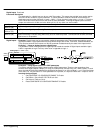
Functional Description
The destination for a digital input can be any valid Tag number. This means that a digital input can be used to
select one of two values for a given parameter. It is also possible to treat the values for true and false as
destination tags from other functions or inputs. 0.00% = a Logic 0 and any other value = a Logic 1. This refers
to the values set in both value for true and value for false parameters. Inverting the digital input is therefore
simple; set value true to 0.00% and value false to 0.01% or any other non–zero number.
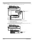
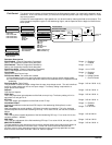
Input
Description
Digital input 1
Terminal (C6)
Jog/Slack digital input. (See Jog/Slack description).
Digital input 2
Terminal (C7)
Jog/Slack mode digital input. (See Jog/Slack description).
Digital input 3
Terminal (C8)
Speed/Torque select input. Closed allows a direct current output command from Analog Input 2. The bipolar
signal from Analog 2 is direct acting without any accel or decel ramp rates. Connection from another command
signal source is not possible.
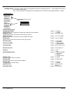
Digital Inputs – Examples Digital inputs can be connected to read/write parameters only. These inputs are useful to control
logical parameters. Logical parameters are those whose ranges are On/Off, True/False, Enabled/Disabled, etc.
They can also send two fixed values to a VALUE parameter as determined by the state of the input terminal.
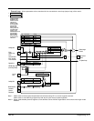
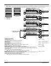
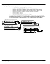
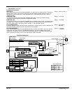
Example 1 – Using an Analog Input as a Digital Input
It is possible to use an Analog Input as a Digital Input to extend the number of Digital Inputs available. Again,
0.00% is regarded as Logic 0 and any other value is regarded as Logic 1.
[231] Max Value +100.00%
[230] Calibration 1.0000
Tag Parameter
[232] Min Value
0.00%
[246] Destination Tag 100
Analog
Input 1
Analog Input 1 – ANIN 1 (A2)
[90]
Bipolar Clamps
Current Loop
Diagnostic
connection
[50]
[246]
A2
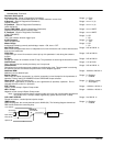
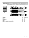
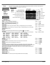
Example 2 – Using digital inputs with LOGIC parameters
The factory settings allow the digital inputs to switch LOGIC parameters. These are the connections from
terminal C6 to tag 90 (Bipolar Clamps), C7 to tag 118 (Ramp Hold), and C8 to tag 119 (I DMD. Isolate). In each
case, the state of the terminal switches the destination parameter on or off by sending a 1 or 0. Since the format
of the Value For True and Value For False parameters is in percent, 0 is equal to 0.00% and 1 is equal to 0.01%.
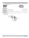
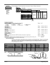
Inverting the Input Signal
1. Set CONFIGURE I/O::CONFIGURE ENABLE To Enable.
2. Set DIGIN 1 (C6)::VALUE FOR TRUE to 0.00%.
3. Set Value for False to 0.01%.
4. Reset CONFIGURE I/O::CONFIGURE ENABLE To Disable.