


5-4 Switch Setting & Start-Up MN792
Power up in Local Mode with Armature Feedback Continued
The control is now ready to run from the keypad using armature feedback.
1. The logic power is still applied, the keypad display is normal, the motor is connected but the load is
removed.
2. Apply 3 phase power.
3. Verify that the keypad and LED displays are still normal, with no error messages.
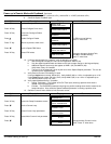
4. Set the Speed Setpoint parameter to zero.
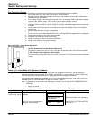
5. Verify that the Main CURR. Limit is set to 0.00%. View ANIN 5 (A6) parameter in the level 1
Diagnostics menu and verify it displays 0.00V.
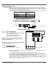
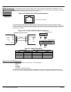
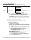
6. Press JOG at the keypad. Verify that 3–phase mains is applied to Power Terminals L1, L2 and L3
and immediately check that the correct field voltage appears between the control supply terminals F+
and F–. If the field voltage is not correct, check one of the following:
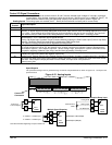
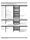
Internally Supplied Field:
a. Check that 3–phase is applied to terminals L1, L2 and L3 when the main contactor is closed.
b. Check that the fuses on the power board or supression board are healthy.
c. Verify the Field Enable parameter is set to Enable.
d. Is the FLD CTRL Mode parameter set to Voltage Control or Current Control?
If set to VOLTAGE CONTROL, check the value of the FLD. VOLTS RATIO parameter. Set this
to 65% to obtain 300V fields from 460V lines.
If set to CURRENT CONTROL, check the field current calibration.
If the field volts are at maximum, check the field continuity. (The field current may initially be
less than the rated value due to a cold field.)
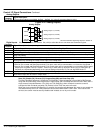
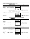
Externally Supplied Field: (not available for size 1and 2 controls)
a. Refer to Chapter 4 Installation, Motor Field Connections for conversion details.
b. Check the voltage applied (externally fused) to terminals FL1 and FL2.
c. Check the phasing of voltage applied to FL1 and FL2:
FL1 must be connected directly or indirectly to the Red phase on main power terminal L1.
FL2 must be connected directly or indirectly to the Yellow phase on main power terminal L2.
d. Verify the Field Enable parameter is set to Enable.
e. Is the FLD CTRL Mode parameter set to Voltage Control or Current Control?
If set to Voltage Control, check the value of the FLD. Volts Ratio parameter. Set this to 65% to
obtain 300V fields from 460V lines.
If set to Current Control, check the field current calibration set–up, refer to “Calibration”.
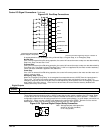
7. Verify that the OK and STOP LEDs are On, also either the FWD or REV LED.
This verifies keypad operation of the control and motor. The control may be used in this mode after the load is
connected or additional wiring changes can be made for operation from the terminal strip.