


6-24 Programming MN792
Digital Inputs Continued
Example 4 – Use Digital Input 1 to switch signal sources
1. Set CONFIGURE I/O::CONFIGURE ENABLE to ENABLE.
2. Set DIGIN 1 (C6)::DESTINATION TAG to 364 (Link 1 source tag parameter).
3. Set DIGIN 1 (C6)::VALUE FOR TRUE to 1.29% (tag number for AUX I/O::ANOUT 2=129).
4. Set DIGIN 1 (C6)::VALUE FOR FALSE to 1.28% (tag number for AUX I/O::ANOUT 1=128).
5. Set LINK 1::DESTINATION TAG to 309 (SETPOINT SUM::INPUT 0 parameter).
6. Set AUX I/O::ANOUT 1 to 10%.
7. Set AUX I/O::ANOUT 2 to 20%.
8. Reset CONFIGURE I/O::CONFIGURE ENABLE to Disable.
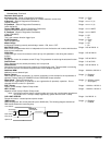
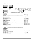
This example uses an internal link to route two signals to Input 0. The state of digital input 1 determines the
number held by LINK 1 :: SOURCE TAG. When true, it is 129. When false, the tag is 128. LINK 1:: SOURCE
TAG retrieves the value from ANOUT 1 or 2 depending on the tag and routes it to SETPOINT SUM 1:: INPUT 0.
The signal switches between 10 and 20 percent. This is useful for switching between two jog setpoints.
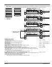
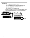
[102] Destination Tag 364
[104] Value for False 1.28%
Tag Parameter Setting
Digital
Input 1
[102]
C6
Digital Input 1 – DIGIN 1 (C6)
[103] Value for True 1.29%
[365] Destination Tag 309
[364] Source Tag 0
Tag Parameter Setting
[365]
System::Configure I/O::Link 1::
Tag Parameter
Setting
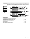
Setup Parameters::AUX I/O::
[128] AUX ANOUT 1 10.00%
[128]
[129] AUX ANOUT 2 20.00%
[129]
[292] Sign 0 Positive
[208] Ratio 0 1.0000
Tag Parameter
Setting
[86]
Setup Parameters::Setpoint Sum 1::
[309] Input 0 0.00% A/B + / -
[420] Divider 0 1.0000
[423] Input 2 0.00%
[100] Input 1 0.00%
+
+
+