


Receiving & Installation 4-9MN792
Electrical Installation Continued
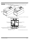
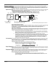
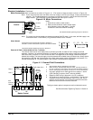
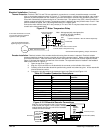
Motor Connections Motor connections are shown in Figure 4-10. (The location of these terminals is shown in Figure 4-9).
Note: If your motor requires more than 85% of the line voltage as its DC input voltage, a step up transformer is
required. This is added between the incoming line terminals and the L1 and L2 terminals of the field
supply module. This connection is phase sensitive with main input L1 and L2.
Figure 4-10 Motor Connections
Notes:
1. Shield wires inside a metal conduit.
2. Metal conduit should be used to shield output
wires (between control and motor). Connect
conduits for continuous EMI/RFI shielding.
Control
Armature
Field
Thermistor
A+
A–
+
F+
F–
+
TH1
TH2
Motor
GND
See Recommended Tightening Torques in Section 9.
Note: The control may be connected to a permanent magnet field DC motor. In this case, the field supply is not
connected and the “Field Enable” [170] parameter must be set to “Disable”.
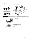
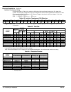
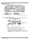
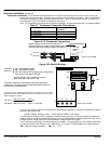
Shunt Wound
Typical shunt wound motor field connection 120/240V or
150/300V. Consult manufacturers specific motor data for details.
120V or 150V
F1 F2
F3 F4
240V or 300V
F1 F4F2 F3
See Recommended Tightening Torques in Section 9.
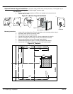
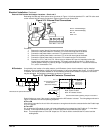
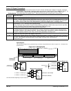
External AC Field (Not available for size 1 controls)
The internal motor field is more widely used, it provides up to 90% of rated AC main voltage to the field
windings. However if an external field supply is required (an application that requires more field voltage than
90% of AC main), terminals FL1 and FL2 can be used. The magnitude of this voltage is determined by the
desired field voltage. The external supply must be protected with suitable fuses and disconnect. Always derive
the supply from the Red and Yellow phases of the main power supply, with the Red phase connected to FL1
and the Yellow phase to FL2 (see jumpers in the External Field Connections diagrams).
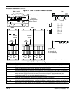
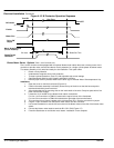
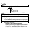
Figure 4-11 External Field Connections
External
Field Supply
L1 L2 L3
L1 L2 L3
Earth
Note 2
Baldor Control
Note 1
Notes:
1. See Protection Device description in this section.
2. Metal conduit or shielded cable should be used. Connect conduits so
the use of a Reactor or RC Device does not interrupt EMI/RFI shielding.
3. Use the same gauge wire for Earth as used for L1, L2, L3 connections.
4. Use same gauge wire for Earth ground as is used for L and N.
(VDE (Germany) requires 10mm
2
minimum, 6AWG).
5. Reference EMC wiring in Appendix A for CE compliance.
6. AC Contactor is internal for size 1 and 2 controls. Size 3–5, the
contactor can be connected between TB3–3 (line) and TB3–4
(neutral) and its purpose is to provide AC power disconnection.
Maximum inrush current must not exceed 3A.
Note 3 & 4
Fuse
Connection
Start
Contactor
TB1
3
RE
4
TB3
This figure shows optional components not furnished with control.
Note 6
FL1 FL2
See Recommended Tightening Torques in Section 9.