


8 Installation In Enclosure
8.2 Layout in Enclosure
102
FX3G Series Programmable Controllers
User's Manual - Hardware Edition
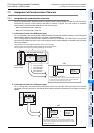
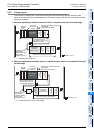
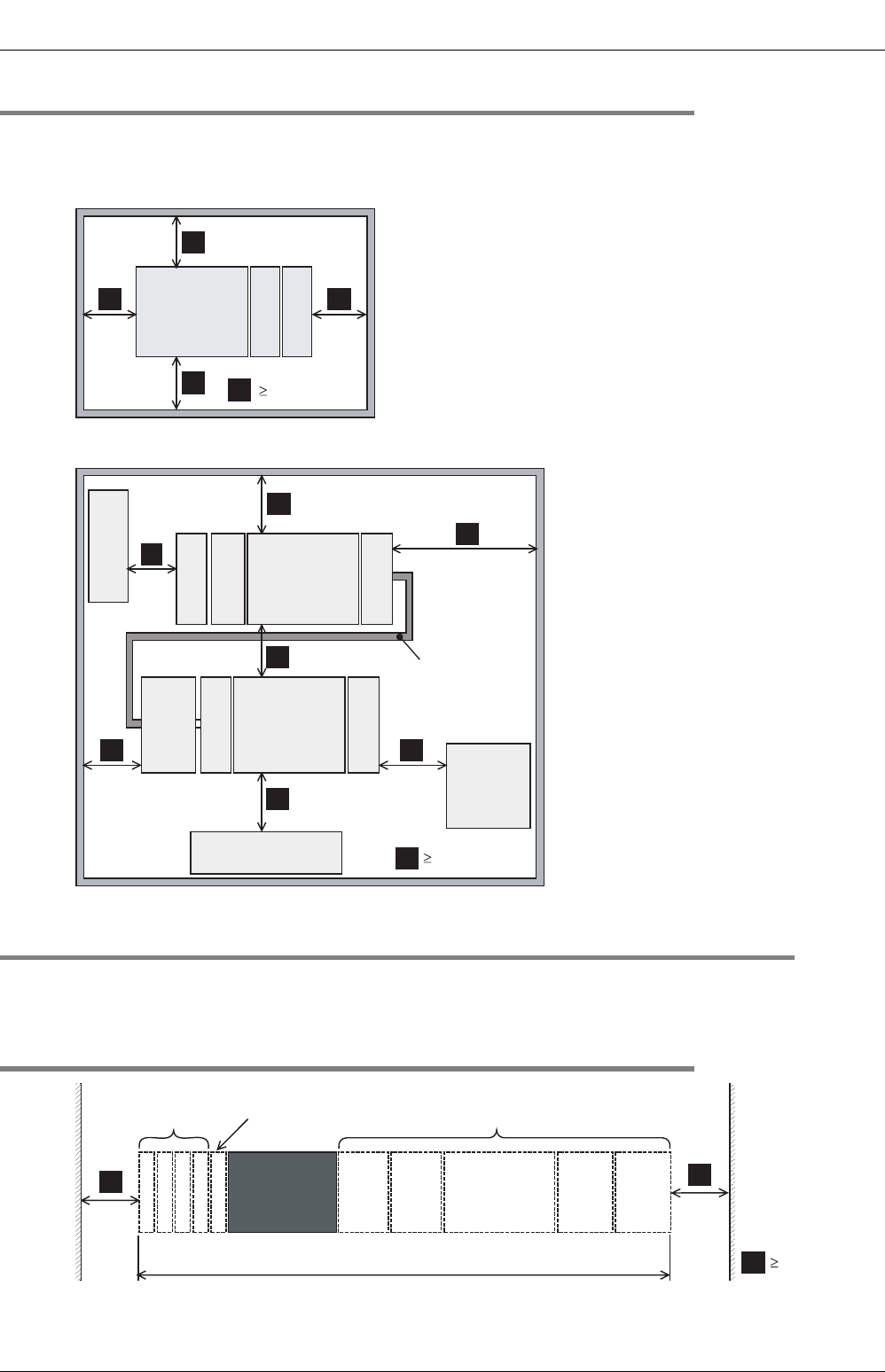
8.1.2 Spaces in enclosure
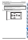
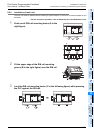
Extension devices can be connected on the left and right sides of the main unit of the PLC.
If you intend to add extension devices, keep necessary spaces on the left and right sides.
1. Configuration without extension cable
2. Configuration in 2 stages with extension cable
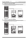
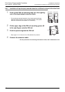
8.2 Layout in Enclosure
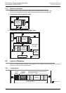
The PLC components can be laid out in one stage or in two stages, upper and lower. The connecting
procedures in each case are explained below.
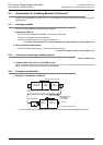
8.2.1 1-stage layout
FX3G Series
main unit
FX2N-16EX
FX2N-16EYT
A
A
A
A
A
50mm (1.97")
Other
equipment
Other
equipment
A
A
A
A
A
Input/output
powered
extension unit
A
Other
equipment
A
FX
3G
Series
main unit
FX3U-4AD-
ADP
FX3G-CNV-
ADP
A
FX
2N
-16EX
Extension cable
·FX
0N
-65EC
·FX
0N
-30EC
FX
2N
-16EYT
FX
2N
-CNV-
BC
50mm (1.97")
FX
3U
-16CCL-M
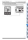
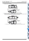
Input/output powered extension units/blocks
Special function blocks
FX3G Series
main unit
Input/output
powered
extension units
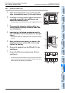
For the dimensions of each product, refer to the
external dimensions.
Special
adapter
Extension
block
Extension
block
Extension
block
Extension
block
A
Connector
conversion
adapter
A
A
50mm (1.97")