


15 Input/Output Powered Extension Units
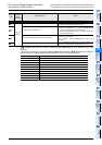
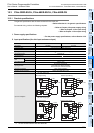
15.2 Power supply specifications
228
FX3G Series Programmable Controllers
User's Manual - Hardware Edition
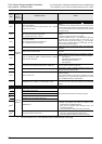
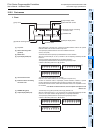
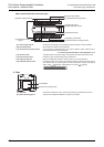
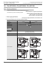
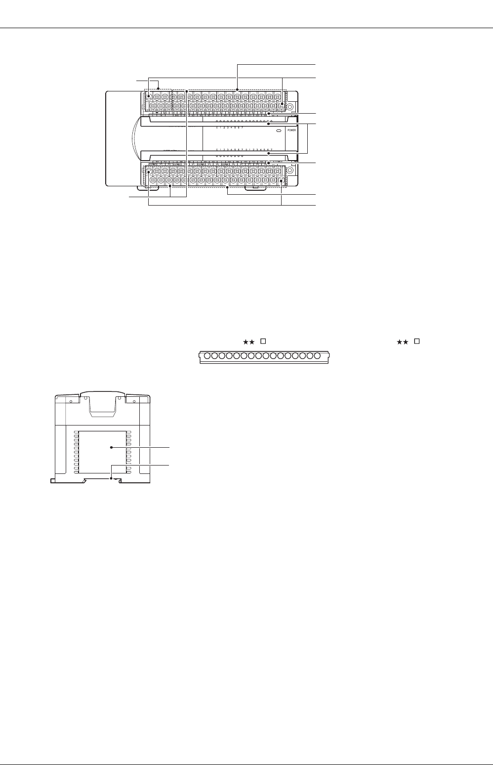
When the terminal block covers are open
2. Side
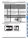
[9] Power supply terminal Connect the power supply to the input/output powered extension unit at this terminal.
[10] Input (X) terminals Wire switches and sensors to these terminals.
[11] Terminal block mounting screws If the input/output powered extension unit must be replaced, loosen these screws to
remove the upper part of the terminal block.
→ For anchoring the terminal block, refer to Subsection 9.1.2.
[12] Terminal names The signal names for the power supply, input terminals and output terminals are shown.
[13] Terminal block covers Protects the upper and lower stages of the terminal block.
[14] Output (Y) terminals Wire the intended loads (contactors, solenoid valves, etc.) to these terminals.
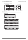
[15] Protective terminal covers A protective terminal cover (refer to the following drawing) is fitted to the lower stage of
each terminal block to prevent fingers from touching terminals, thereby improving the
safety. (FX2N- E -ES(S)/UL, FX2N-48ER-UA1/UL, FX2N- E -DS(S))
[1] Nameplate The product model name, control number and power supply specifications are shown.
[2] DIN rail mounting groove The unit can be installed on DIN46277 rail (35mm (1.38") wide).
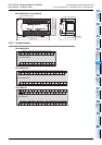
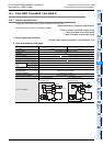
[12] Terminal names
[9] Power supply terminal
[11] Terminal block mounting screws
[11] Terminal block fitting screws
[10] Input (X) terminals
[12] Terminal names
[13] Terminal block covers
[14] Output (Y) terminals
[15] Protective terminal
covers
[1] Nameplate
[2] DIN rail mounting groove