


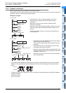
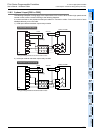
12 Output Wiring Procedures
173
FX3G Series Programmable Controllers
User's Manual - Hardware Edition
11
High-Speed
Counters
12
Output Wiring
13
Wiring for
Various Uses
14
Test Run,
Maintenance,
Troubleshooting
15
Input/Output
Powered
Extension Units
16
Input/Output
Extension
Blocks
17
Extension
Power Supply
Unit
18
Other Extension
Units and
Options
19
Display Module
20
Terminal Block
WIRING PRECAUTIONS
• Do not supply power to the [24+] and [24V] terminals (24V DC service power supply) on the main unit or extension units.
Doing so may cause damage to the product.
• Perform class D grounding (grounding resistance: 100 or less) to the grounding terminal on the main unit and extension units with a
wire 2 mm
2
or thicker.
Do not use common grounding with heavy electrical systems (refer to section 9.3).
• Do not wire vacant terminals externally.
Doing so may damage the product.
• Connect the AC power supply wiring to the dedicated terminals described in this manual.
If an AC power supply is connected to a DC input/output terminal or DC power supply terminal, the PLC will burn out.
• Connect the DC power supply wiring to the dedicated terminals described in this manual.
If an AC power supply is connected to a DC input/output terminal or DC power supply terminal, the PLC will burn out.
• When drilling screw holes or wiring, make sure cutting or wire debris does not enter the ventilation slits.
Failure to do so may cause fire, equipment failures or malfunctions.
• Make sure to properly wire the FX3G Series main unit and FX2N/FX3U Series extension equipment in accordance with the following
precautions.
Failure to do so may cause electric shock, equipment failures, a short-circuit, wire breakage, malfunctions, or damage to the product.
- The disposal size of the cable end should follow the dimensions described in the manual.
- Tightening torque should follow the specifications in the manual.
- Tighten the screws using a Phillips-head screwdriver No.2 (shaft diameter 6mm (0.24") or less). Make sure that the screwdriver
does not touch the partition part of the terminal block.
• Make sure to properly wire to the terminal block (European type) in accordance with the following precautions.
Failure to do so may cause electric shock, equipment failures, a short-circuit, wire breakage, malfunctions, or damage to the product.
- The disposal size of the cable end should follow the dimensions described in the manual.
- Tightening torque should follow the specifications in the manual.
- Twist the end of strand wire and make sure that there are no loose wires.
- Do not solder-plate the electric wire ends.
- Do not connect more than the specified number of wires or electric wires of unspecified size.
- Affix the electric wires so that neither the terminal block nor the connected parts are directly stressed.
• Make sure to properly wire to the FX Series terminal blocks in accordance with the following precautions.
Failure to do so may cause electric shock, equipment failures, a short-circuit, wire breakage, malfunctions, or damage to the product.
- The disposal size of the cable end should follow the dimensions described in the manual.
- Tightening torque should follow the specifications in the manual.
- Tighten the screws using a Phillips-head screwdriver No.2 (shaft diameter 6mm (0.24") or less). Make sure that the screwdriver
does not touch the partition part of the terminal block.