


8 Installation In Enclosure
8.3 Examination for Installing Method in Enclosure
104
FX3G Series Programmable Controllers
User's Manual - Hardware Edition
8.3 Examination for Installing Method in Enclosure
Examine the installation location of PLC in consideration of the environmental conditions (generic
specifications).
8.3.1 Installing methods
The PLC can be installed by the following two methods.
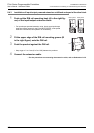
1. Installing on DIN rail
• The PLC can be installed on a DIN46277 rail (35 mm (1.38") wide).
• The PLC can be easily moved and removed.
• The PLC is installed higher by the height of the DIN rail.
→ For details on the procedures on mounting and removing the DIN rail, refer to Section 8.4.
2. Direct installing (with screws)
• The PLC can be installed directly in the enclosure with M4 screws.
→ For the mounting hole pitch, refer to Section 8.5.
8.3.2 Cautions on examining installing method
→ Refer to Section 8.2.
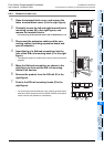
1. Cautions when FX3U-4LC or FX2N-8AD is used
When the system is laid out in two stages, do not mount the FX3U-4LC or FX2N-8AD at the start of the second
stage, or else the FX
2N-CNV-BC cannot be secured properly.
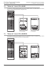
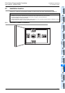
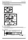
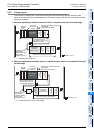
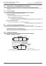
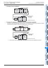
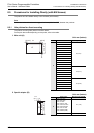
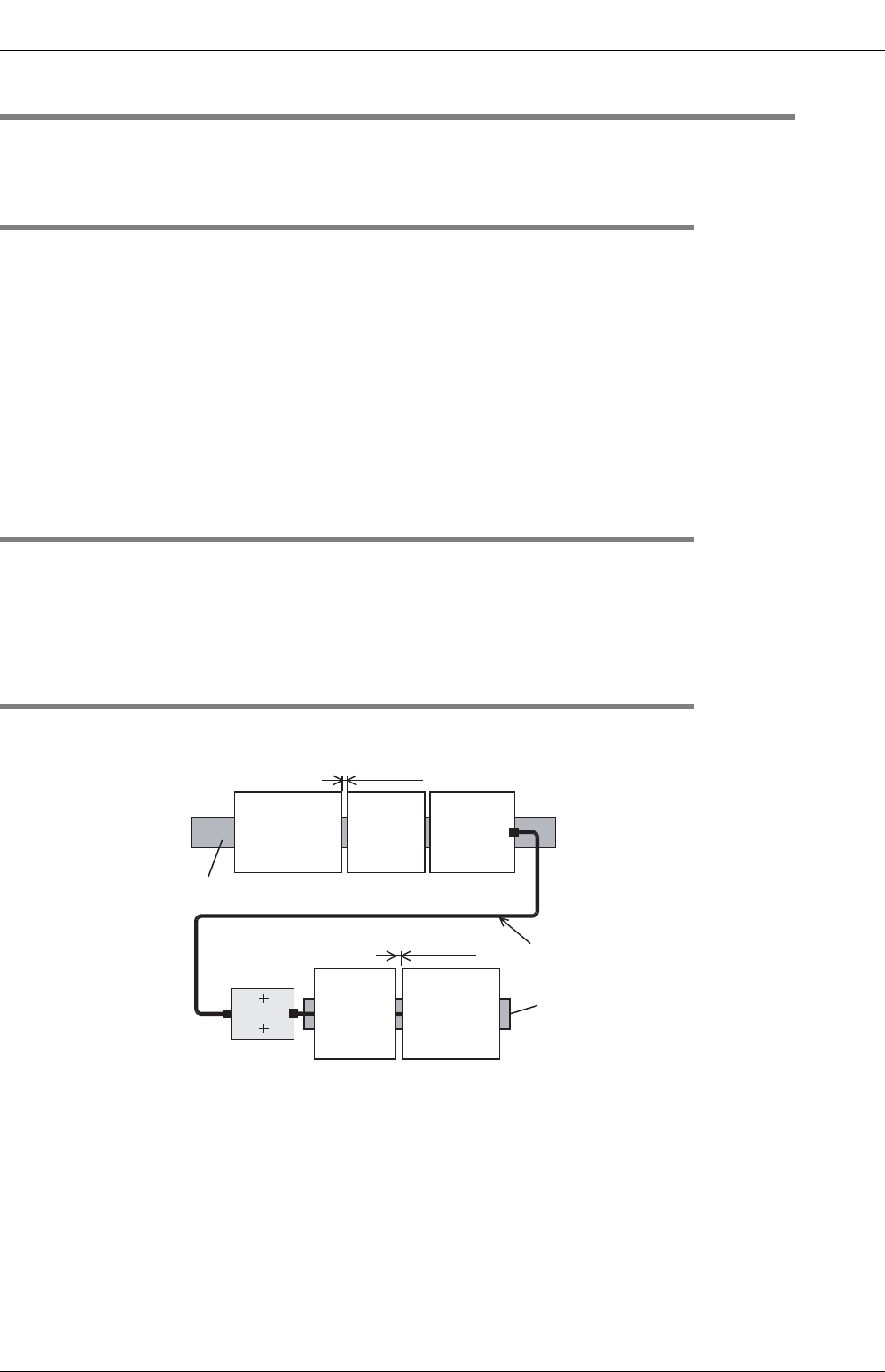
8.3.3 Examples of installation
1. Example of installation on DIN rail
*1. FX2N-CNV-BC can be installed directly in the enclosure but cannot be installed on the DIN rail.
FX3G Series
main unit
DIN rail
Extension cable
·FX
0N-65EC
·FX
0N-30EC
FX2N-CNV-BC
*1
FX2N-
16EYT
FX2N-
16EX
FX2N-
16EX
FX2N-
64CL-M
DIN rail
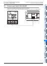
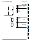
(+ indicates an M4 screw.)
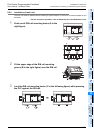
1 to 2mm (0.04" to 0.08")
1 to 2mm
(0.04" to 0.08")