


15 Input/Output Powered Extension Units
15.8 FX2N-48ER-UA1/UL
244
FX3G Series Programmable Controllers
User's Manual - Hardware Edition
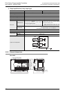
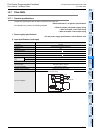
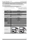
3. Output specifications (relay output type)
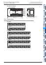
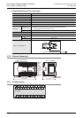
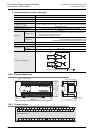
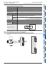
15.8.2 External dimensions
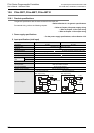
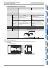
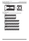
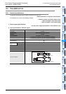
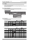
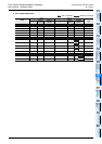
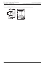
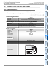
15.8.3 Terminal layout
Item FX2N-48ER-UA1/UL
Output Points 24 points
Connection type Removable terminal block (M3 screw)
Output unit Relay
External power supply
30V DC or less
240V AC or less (250V AC or less when the unit does not comply with CE, UL or cUL standards)
Output circuit insulation Mechanical insulation
Indication of output operation Supplying power to the relay coil will light the LED indicator lamp on panel.
Max. load
Resistance load
2A/point
The total load current of resistance loads per common terminal should be the following value.
• 4 output points/common terminal: 8A or less
• 8 output points/common terminal: 8A or less
Inductive load
80VA
→ For the product life, refer to Subsection 14.4.3.
→ For cautions on external wiring, refer to Subsection 12.1.2.
Open circuit leakage current -
Min. load 5V DC, 2mA (reference value)
Response time
OFF ON
Approx. 10ms
ON OFF
Approx. 10ms
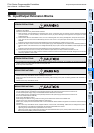
Output circuit configuration
External
power supply
Load
Fuse
Y
COM
DC power
supply
Fuse
Y
COM
A common number applies to the of [COM ].
220 (8.67")
210 (8.27") (mounting hole pitch)
80 (3.15")
(mounting hole pitch)
90 (3.55")
9 (0.36")
Unit : mm (inches)
87 (3.43")
4-
4.5 mounting holes
COMCOM
NL
X0
X1
X2
X3
X4
X5
X6
X7
X0
X1
Y4Y2
Y3Y1
Y0
Y5
Y6
Y7
Y0
Y1
Y2
Y3
X2
X3
X4
X5
X6
X7
Y4
Y5
Y6
Y7
FX
2N
-48ER-UA1/UL
X0
X1
X2
X3
X4
X5
X6
X7
COM1 COM2 COM3 COM4
Y0
Y1
Y2
Y3
COM5
Y4
Y5
Y6
Y7