


2 Features and Part Names
2.1 Major Features
29
FX3G Series Programmable Controllers
User's Manual - Hardware Edition
1
Introduction
2
Features and
Part Names
3
Product
Introduction
4
Specifications
5
Version and
Peripheral
Devices
6
System
Configuration
7
Input/Output
Nos., Unit Nos.
8
Installation
9
Preparation and
Power Supply
Wiring
10
Input Wiring
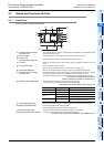
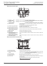
2. Features and Part Names
2.1 Major Features
1. Basic functions
[Up to 256 input/output points]
The total number of inputs and outputs (128
points maximum) directly connected to the PLC
and remote inputs and outputs (128 points
maximum) of the CC-Link can be extended to
256 points.
[Program memory]
The PLC has a 32K-step EEPROM memory.
[Built-in USB port]
The PLC has a built-in USB port for the
programming communication function to enable
high-speed communication at 12Mbps.
[Built-in RUN/STOP switch]
The PLC can be started and stopped with the
built-in switch.
RUN and STOP commands can be given to the
PLC through a general-purpose input terminal or
peripheral device.
[Built-in Variable analog potentiometers]
The PLC has two built-in variable analog
potentiometers available for adjusting the timer
set time.
[Writing during RUN]
The programming software for personal
computer enables you to modify the program
while the PLC is running.
[Built-in clock function]
The PLC has a clock function to control the time.
[Programming tool]
Use a version of a programming tool supporting
the FX
3G.
→ Refer to 5. Version Information and
Peripheral Equipment Connectability in this
manual.
*For peripheral devices not applicable to FX
3G
Series, specify FX1N Series for model selection,
and you can program the sequence.
In this case, use instructions and devices within
the ranges common to FX
3G Series and the
selected model of PLC.
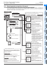
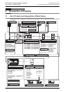
[Remote debugging of program]
Use of programming software (GX Works2, GX
Developer) enables you to remotely transfer
programs and monitor PLC operation through a
modem connected to the RS-232C expansion
board or RS-232C communication special
adapter.
2. Input/output high-speed processing
functions of main unit
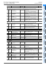
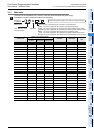
[High-speed counter function]
Input terminals of main unit
- Input of open collector transistor output
- 1-phase 60kHz x 4 points + 10kHz x 2 points
- 2-phase 30kHz x 2 points + 5kHz x 1 points
→ Refer to 11. Use of High-speed Counters in
this manual and Programming Manual.
[Pulse catch function]
Signals with short ON width or OFF width can be
captured without a complicated program.
→ Refer to 10. Input Wiring Procedures
in this manual and Programming Manual.
[Input interruption function]
The PLC can process interruption routines with
higher priority using external signals whose
minimum ON duration or OFF duration is 10 s
(X000, X001, X003 and X004) or 50 s (X002
and X005). (The timer interruption function is
also provided.)
→ Refer to 10. Input Wiring Procedures in
this manual and Programming Manual.
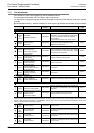
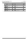
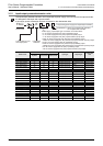
[Pulse width/period measurement function]
(Supported in Ver. 1.10 or later)
The width/period of pulses from input terminals
(X000, X001, X003 and X004) of the main unit
can be measured in units of 10 s.
→ Refer to 10. Input Wiring Procedures and
Programming Manual.
Input terminal Signal ON/OFF width
X000, X001, X003, X004 10 s
X002, X005 50 s