


12 Output Wiring Procedures
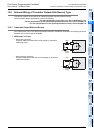
12.2 External Wiring of Transistor Output (Sink/Source) Type
178
FX3G Series Programmable Controllers
User's Manual - Hardware Edition
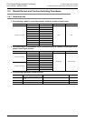
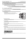
12.2.2 Handling of transistor output
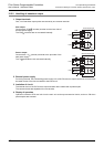
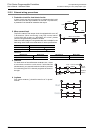
1. Output terminals
One, 4 or 8 transistor output points are covered by one common terminal.
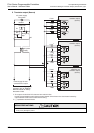
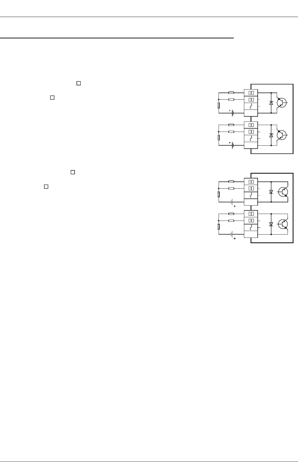
Sink output
Connect each COM (number) terminal to the minus side of
the load power supply.
The COM terminals are not connected internally.
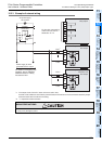
Source output
Connect each +V (number) terminal to the plus side of the
load power supply.
The +V terminals are not connected internally.
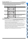
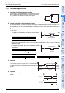
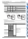
2. External power supply
For driving the load, use a smoothing power supply of 5 to 30V DC that can output current two or more times
the rated current of the fuse connected to the load circuit.
3. Insulation of circuit
The internal circuit of the PLC and the output transistor are insulated with a photocoupler.
The common blocks are separated from one another.
4. Display of operation
Operation indicator LEDs are built into the main unit and output extension blocks, and turn ON when
photocouplers are actuated.
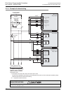
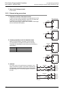
PLC
Load
DC power
supply
Fuse
Y 0
COM1
Load
Fuse
COM2
Sink output type
DC power
supply
Y 1
Y 5
Y 4
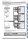
PLC
Load
DC power
supply
Fuse
+V0
Load
DC power
supply
Fuse
+V1
Source output type
Y 0
Y 1
Y 5
Y 4