314
FX3S/FX3G/FX3GC/FX3U/FX3UC Series
Programming Manual - Basic & Applied Instruction Edition
11 Rotation and Shift Operation – FNC 30 to FNC 39
11.10 FNC 39 – SFRD / Shift Read [FIFO Control]
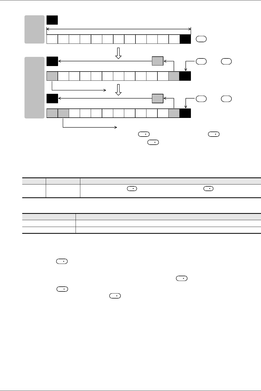
1) When the command input turns ON, the contents of +1 are transferred (read) to .
2) Accompanied by this transfer, the contents of the pointer decrease, and the data on the left side are shifted
rightward by 1 word. (When the continuous operation type SFRD instruction is used, the contents are stored in
turn in each operation cycle. Use the pulse operation type SFRDP instruction in programming.)
Related device
→ For the zero flag use method, refer to Subsection 6.5.2.
Related instructions
Caution
1. Data after reading was executed
The contents of +n do not change by reading.
2. In the case of continuous operation type (SFRD) instruction
Data is read in turn in each scan time (operation cycle), but the contents of +n do not change.
3. When pointer is 0
Data is not processed, and the contents of do not change.
Program example
Refer to the program example provided for SFWR (FNC 38) instruction.
→ For the program example, refer to Section 11.9.
Device Name Description
M8020 Zero
Data is always read from +1. When the contents of the pointer become "0", the zero flag
M8020 turns ON.
Instruction Description
SFWR (FNC 38) Shift write (for FIFO/FILO control)
POP (FNC212) Shift last data read (for FILO control)
S
S+n ... S+2S+10 S+9 S+8 S+7 S+6 S+5 S+4 S+3 S+1
D
n
D
S
S+n ... S+2S+10 S+9 S+8 S+7 S+6 S+5 S+4 S+3S+n
D
S
S+n ... S+10 S+9 S+8 S+7 S+6 S+5 S+4 S+3S+nS+n
−
1
→
Executed at the 2nd time
Executed at the 1st time
S+2
Word data is shifted.
Word data is shifted.
S+1
S
= n
Pointer
Pointer
Pointer
Before
execution
After
execution
S
S
−
1
→
S
S
S
D
S
S
S
S
S
S
D


