


12 Output Wiring Procedures
12.2 External Wiring of Transistor Output (Sink/Source) Type
181
FX3G Series Programmable Controllers
User's Manual - Hardware Edition
11
High-Speed
Counters
12
Output Wiring
13
Wiring for
Various Uses
14
Test Run,
Maintenance,
Troubleshooting
15
Input/Output
Powered
Extension Units
16
Input/Output
Extension
Blocks
17
Extension
Power Supply
Unit
18
Other Extension
Units and
Options
19
Display Module
20
Terminal Block
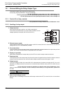
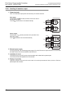
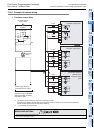
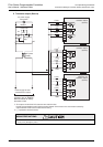
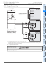
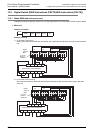
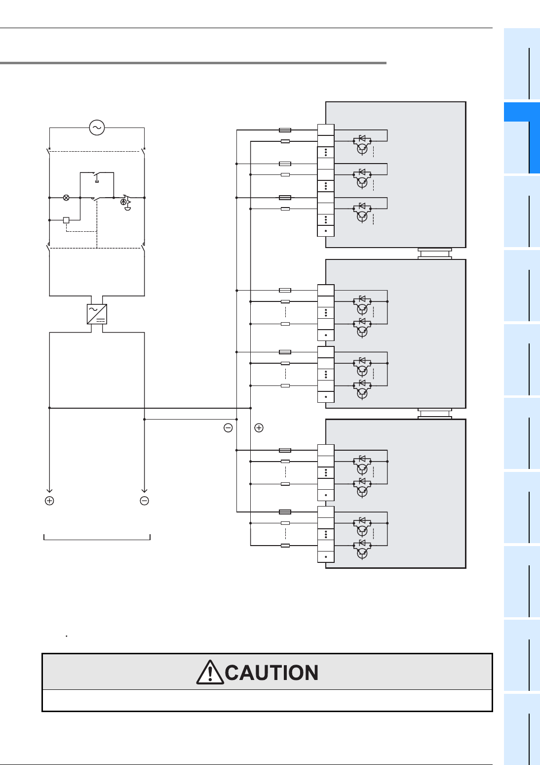
12.2.4 Example of external wiring
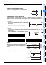
1. Transistor output (Sink)
WIRING PRECAUTIONS
• Do not wire the vacant terminals externally.
Doing so may damage the product.
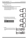
Output extension block
transistor output (sink)
Y0
COM1
Y7
Y0
COM2
Y7
Y0
COM1
Y7
Y0
COM2
Y7
Load
PL
Power ON
Emergency
stop
MC
MC
MC MC
DC power
supply
Power supply for load
connected to PLC output
For details on emergency stop
operation, refer to "DESIGN
PRECAUTIONS" at "Safety
Precautions" field.
Load
Load
Load
The output circuit of this PLC does not have a built-in fuse.
Provide a fuse suitable to each load to prevent blowout of the wires on the circuit board caused by
output element fracture due to load short-circuiting.
" " represents vacant terminals.
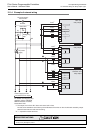
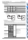
Input/output powered
extension unit
transistor output
(sink)
Fuse
*1
Fuse
*1
Fuse
*1
Fuse
*1
Load
Load
Fuse
*1
Fuse
*1
AC power supply
100 to 240V
Breaker
*2
*2
*2
*2
Main unit
transistor output (sink)
Y0
COM0
Y10
COM4
Y2
COM2
*2
*1.
*2.