


8 Installation In Enclosure
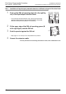
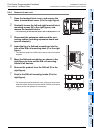
8.5 Procedures for Installing Directly (with M4 Screws)
110
FX3G Series Programmable Controllers
User's Manual - Hardware Edition
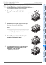
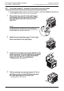
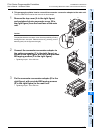
8.5 Procedures for Installing Directly (with M4 Screws)
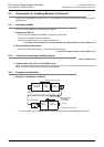
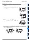
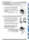
The product can be installed directly in the enclosure (with screws).
Point
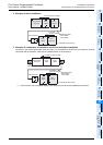
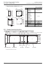
Position the holes so that there is a gap of 1 to 2 mm (0.04" to 0.08") between the products.
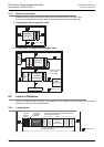
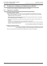
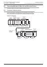
8.5.1 Hole pitches for direct mounting
The product mounting hole pitches are shown below.
For the pitch that varies depending on the product, refer to the table.
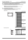
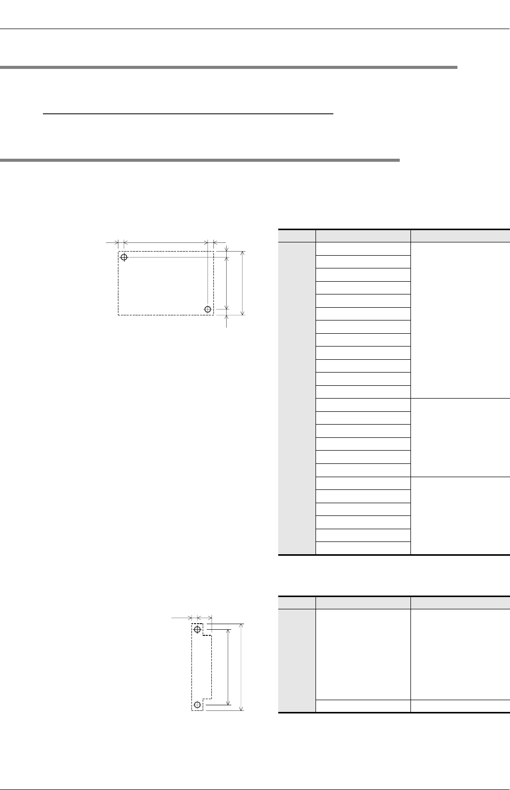
1. Main unit (A)
Unit: mm (inches)
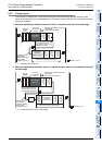
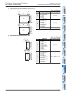
2. Special adapter (B)
Unit: mm (inches)
Model name Mounting hole pitch(W)
A
FX3G-14MR/ES
82 (3.23")
FX3G-14MT/ES
FX3G-14MT/ESS
FX3G-14MR/DS
FX3G-14MT/DS
FX3G-14MT/DSS
FX3G-24MR/ES
FX3G-24MT/ES
FX3G-24MT/ESS
FX3G-24MR/DS
FX3G-24MT/DS
FX3G-24MT/DSS
FX3G-40MR/ES
122 (4.81")
FX3G-40MT/ES
FX3G-40MT/ESS
FX3G-40MR/DS
FX3G-40MT/DS
FX3G-40MT/DSS
FX3G-60MR/ES
167 (6.58")
FX
3G-60MT/ES
FX
3G-60MT/ESS
FX3G-60MR/DS
FX3G-60MT/DS
FX
3G-60MT/DSS
Model name Mounting hole pitch(W)
B
FX3U-4AD-ADP
FX3U-4DA-ADP
FX3U-3A-ADP
FX3U-4AD-PT-ADP
FX3U-4AD-PTW-ADP
FX3U-4AD-PNK-ADP
FX3U-4AD-TC-ADP
FX3U-232ADP(-MB)
FX3U-485ADP(-MB)
15.1 (0.6")
FX3U-ENET-ADP 20.5 (0.89")
W
A
4(0.16")
82 (3.23")
90 (3.55")
4(0.16")
4(0.16")
B
98 (3.86")
W
2.5
(0.1")
106 (4.18")