


13 Examples of Wiring for Various Uses
196
FX3G Series Programmable Controllers
User's Manual - Hardware Edition
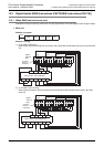
13.4 Seven Segment with Latch [SEGL Instructions (FNC74)/BCD Instructions (FNC18)]
2. Input/output powered extension unit
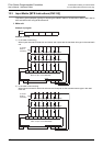
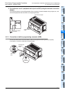
Example of program
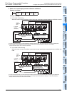
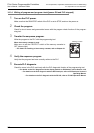
Example of wiring
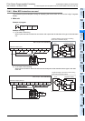
1) In the case of sink wiring
When inputs are used for sink only and outputs are the transistor sink type in the used input/output
powered extension unit
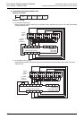
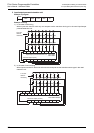
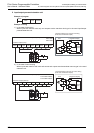
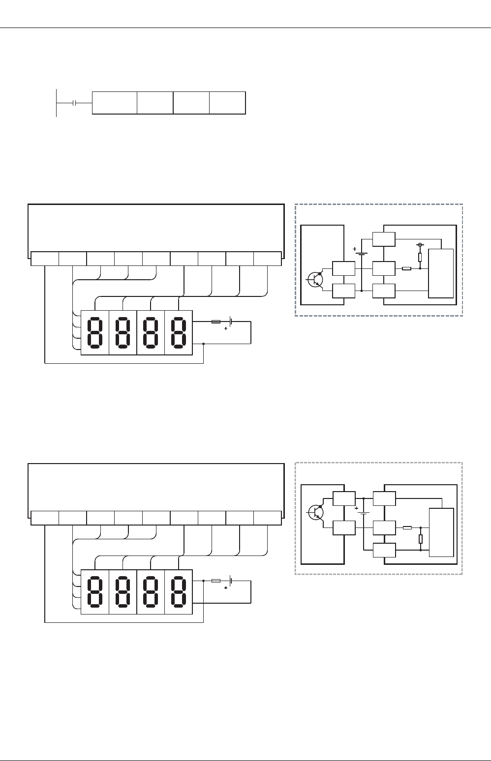
2) In the case of source wiring
When inputs are used for both sink and source and outputs are the transistor source type in the used
extension unit
M8000
D100 Y020 K1SEGL
10
3
10
2
10
1
10
0
124
8
10
3
10
2
10
1
10
0
1
2
4
Y020COM1 Y021 Y022 Y023 Y024 Y025 Y026 Y027
8
Transistor output (sink)
*
* Use a 7-segment display with a latch and a built-in BCD decoder.
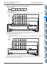
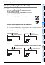
Input/output powered extension unit
FX
2N
-32ET
FX
2N
-48ET
Signal
-
Internal
circuit
7-segment display
+
Y
COM1
PLC
7-segment display to be used for sink wiring
(in the case of transistor output)
10
3
10
2
10
1
10
0
124
8
10
3
10
2
10
1
10
0
1
2
4
Y020+V0 Y021 Y022 Y023 Y024 Y025 Y026 Y027
8
Transistor output (source)
*
* Use a 7-segment display with a latch and a built-in BCD decoder.
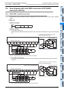
Signal
-
7-segment display
+
Y
PLC
7-segment display to be used for source wiring
(in the case of transistor output)
+V0
Internal
circuit
Input/output powered extension unit
FX
2N-32ET-ESS/UL
FX
2N-48ET-ESS/UL