


8 Installation In Enclosure
8.2 Layout in Enclosure
103
FX3G Series Programmable Controllers
User's Manual - Hardware Edition
1
Introduction
2
Features and
Part Names
3
Product
Introduction
4
Specifications
5
Version and
Peripheral
Devices
6
System
Configuration
7
Input/Output
Nos., Unit Nos.
8
Installation
9
Preparation and
Power Supply
Wiring
10
Input Wiring
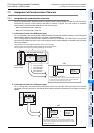
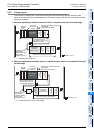
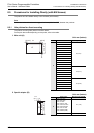
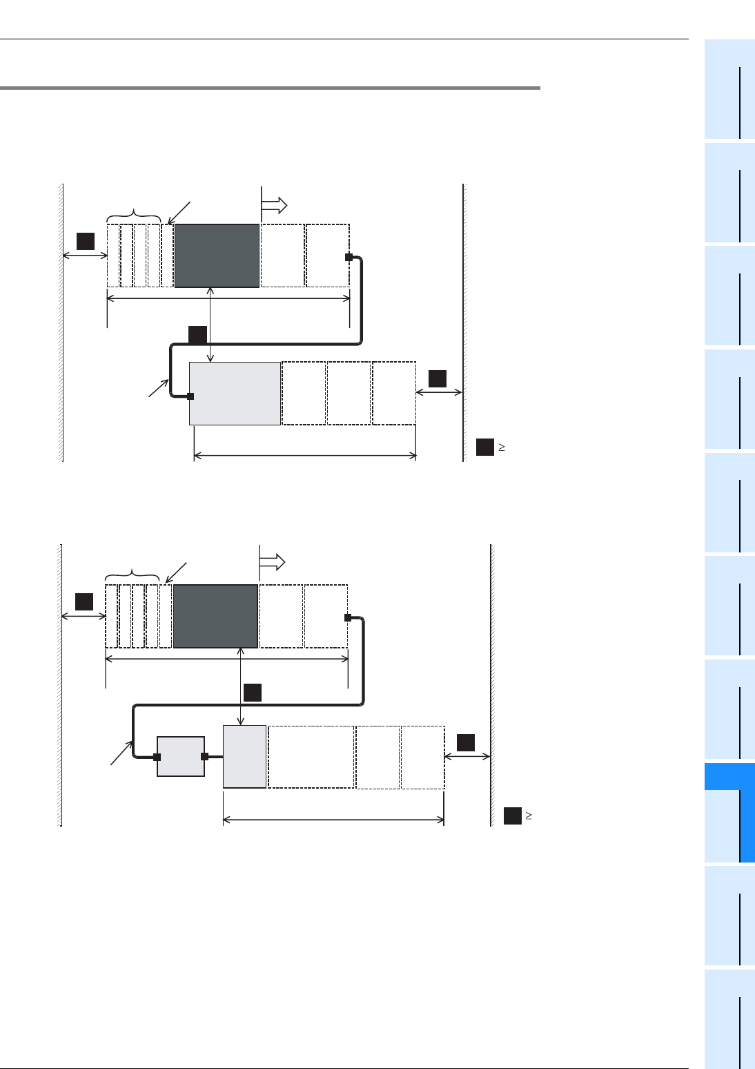
8.2.2 2-stage layout
In the case of a 2-stage layout, connect the first stage and the second stage with the extension cable.
When an extension block is connected at the top of the second stage, FX
2N-CNV-BC (connector conversion
adapter) is necessary.
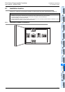
1. When an input/output powered extension unit is connected at the top of the 2nd stage
*1. Including FX3U-1PSU-5V
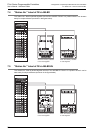
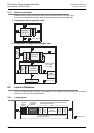
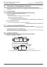
2. When an input/output extension block or a special function block is connected at the top of
the 2nd stage
*2. Except for the FX3U-4LC or FX2N-8AD
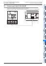
A
50mm (1.97")
FX3G Series
main unit
For the dimensions of
each product, refer to the
external dimensions.
Extension
block
Extension
block
A
Special
adapter
A
Input/output powered extension
units/blocks
Special function blocks
Connector
conversion
adapter
Input/output
powered
extension units
*1
For the dimensions of each product,
refer to the external dimensions.
Extension cable
·FX
0N-65EC
(650mm(25.59"))
·FX
0N-30EC
(300mm(11.81"))
Extension
block
Extension
block
Extension
block
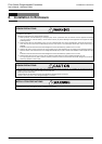
A
A
50mm (1.97")
Input/output powered extension
units/blocks
Special function blocks
FX3G Series
main unit
For the dimensions of
each product, refer to
the external dimensions.
Extension
block
Extension
block
A
Special
adapter
Connector
conversion
adapter
A
FX2N-CNV-BC
A
Extension
block
*2
Input/output
powered
extension units
For the dimensions of each product,
refer to the external dimensions.
Extension
block
Extension
block
Extension cable
·FX
0N-65EC
(650mm(25.59"))
·FX
0N-30EC
(300mm(11.81"))