


21 Memory Cassette
377
FX3G Series Programmable Controllers
User's Manual - Hardware Edition
21
Memory
Cassette
22
Battery
A
Special Devices
(M8000-,D8000-)
B
Instruction List
C
Discontinued
models
D
Precautions for
battery
transportation
E
Handling of
batteries in EU
member states
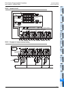
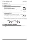
21.3 Installation
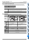
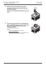
5 The memory cassette (E in the right figure) can
be fixed with provided M3 tapping screws (D in
the right figure) to the main unit. This work is
not required when fixation is not necessary.
• Tightening torque : 0.3 to 0.6 N•m
Caution:
- Two types of M3 tapping screws are provided.
Use M3 8 (shorter) screws.
Do not use M3 16 (longer) screws because they may
damage the main unit.
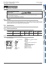
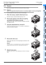
21.3.2 Installation
(when the expansion board/connector conversion adapter is used together)
The FX3G-40MT/ES is used as the main unit and the expansion board is used together in this example.
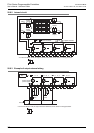
1 Attach the expansion board/connector conversion adapter to the main unit.
→ For the attachment method, refer to Chapter 8.
Caution:
Make sure to attach the expansion board/connector conversion adapter before the memory cassette.
Tightening with tapping screws (M3 8) is not necessary.
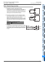
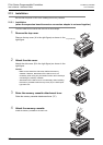
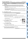
2 Remove the upper connector cover (A in the
right figure).
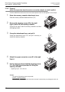
3 Remove the part B shown in the right figure
using nipper, etc.
Caution:
Removal of the part B is not necessary when the connector
conversion adapter is used together.
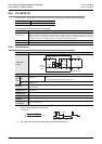
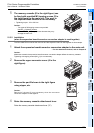
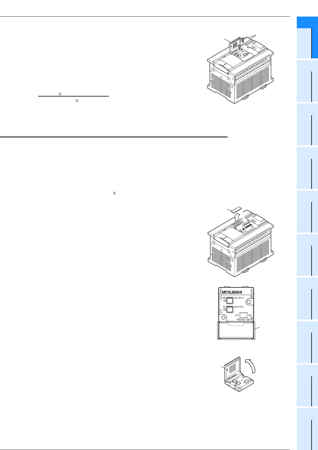
4 Raise the memory cassette detachment lever.
Raise the memory cassette detachment lever ("C").
D
E
2
A
B
4
C