


17 Extension Power Supply Unit
17.1 Outline
284
FX3G Series Programmable Controllers
User's Manual - Hardware Edition
17. Extension Power Supply Unit
17.1 Outline
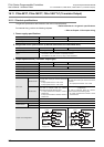
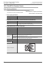
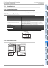
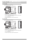
When the internal power supplied from the FX3G Series PLC (AC power supply type) is insufficient for
powering output extension blocks or special function blocks, the FX
3U-1PSU-5V (extension power supply
unit) is available.
Only one FX
3U-1PSU-5V unit may be connected to a FX3G PLC system.
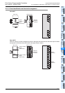
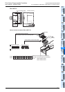
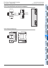
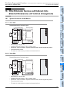
Connect extension equipment to the FX
3U-1PSU-5V according to the configuration specification limits
described in Subsection 17.2.2.
→ For the system configuration with FX
3U-1PSU-5V, refer to Chapter 6.
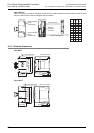
→ For the mounting, refer to Chapter 8.
→ For the wiring, refer to Chapter 9.
DESIGN PRECAUTIONS
• Make sure to have the following safety circuits outside of the PLC to ensure safe system operation even during external power supply
problems or PLC failure.
Otherwise, malfunctions may cause serious accidents.
1) Most importantly, have the following: an emergency stop circuit, a protection circuit, an interlock circuit for opposite movements
(such as normal vs. reverse rotation), and an interlock circuit (to prevent damage to the equipment at the upper and lower
positioning limits).
2) Note that when the PLC CPU detects an error, such as a watchdog timer error, during self-diagnosis, all outputs are turned off.
Also, when an error that cannot be detected by the PLC CPU occurs in an input/output control block, output control may be
disabled.
External circuits and mechanisms should be designed to ensure safe machinery operation in such a case.
3) Note that the output current of the 24V DC service power supply varies depending on the model and the absence/presence of
extension blocks. If an overload occurs, the voltage automatically drops, inputs in the PLC are disabled, and all outputs are turned
off.
External circuits and mechanisms should be designed to ensure safe machinery operation in such a case.
4) Note that when an error occurs in a relay, triac or transistor output device, the output could be held either on or off.
For output signals that may lead to serious accidents, external circuits and mechanisms should be designed to ensure safe
machinery operation in such a case.
DESIGN PRECAUTIONS
• Do not bundle the control line together with or lay it close to the main circuit or power line. As a guideline, lay the control line at least
100mm (3.94") or more away from the main circuit or power line.
Noise may cause malfunctions.