


11 Use of High-speed Counters
11.10 Cautions on Use
171
FX3G Series Programmable Controllers
User's Manual - Hardware Edition
11
High-Speed
Counters
12
Output Wiring
13
Wiring for
Various Uses
14
Test Run,
Maintenance,
Troubleshooting
15
Input/Output
Powered
Extension Units
16
Input/Output
Extension
Blocks
17
Extension
Power Supply
Unit
18
Other Extension
Units and
Options
19
Display Module
20
Terminal Block
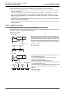
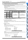
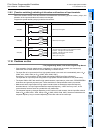
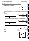
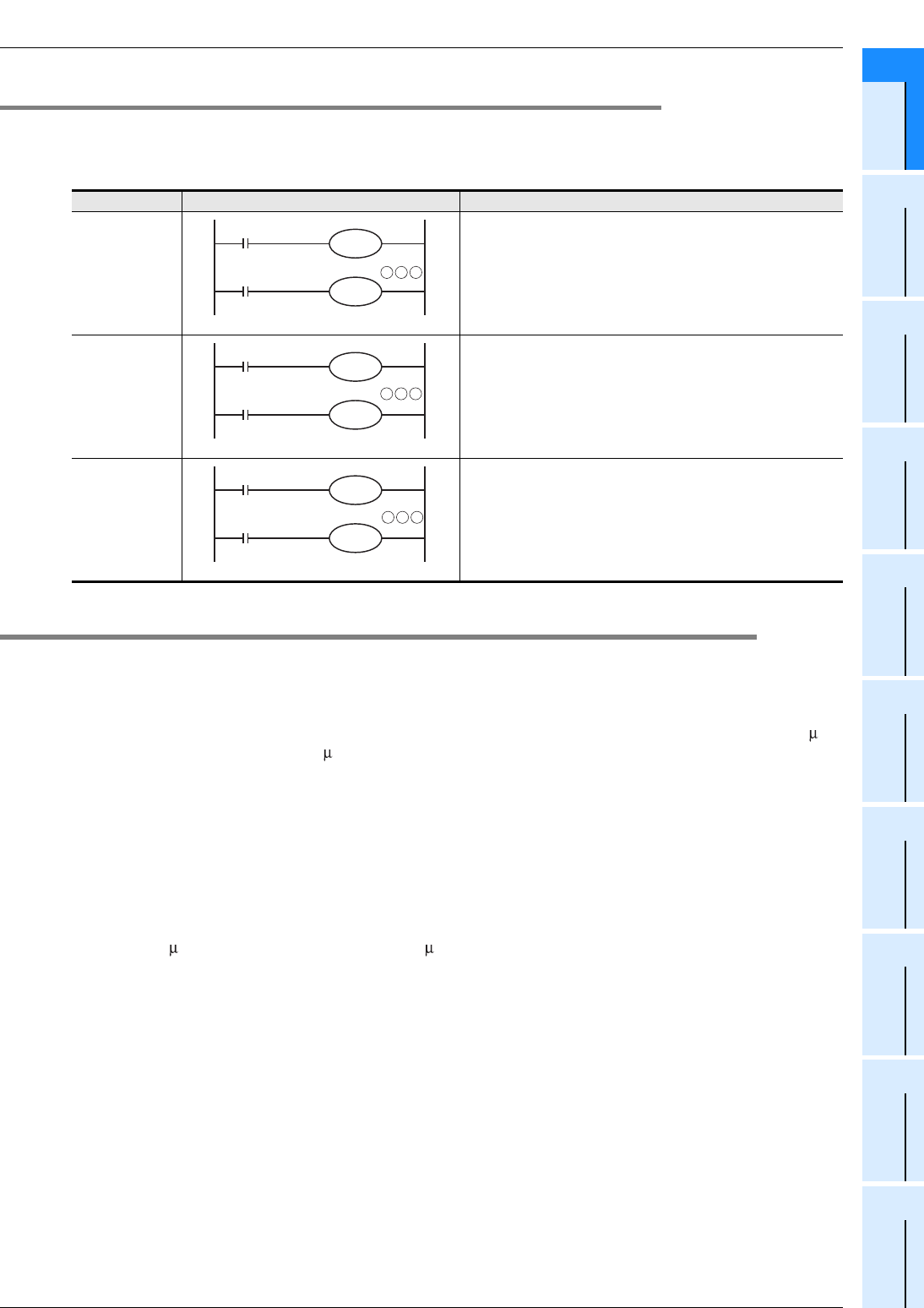
11.9.2 [Function switching] switching of allocation and functions of input terminals
When the counters C248, C253 and C254 are combined with the following special auxiliary relays, the
allocation of the input terminals and functions are changed.
Program the special auxiliary relays just before the counters.
11.10 Cautions on Use
→ For programming details, refer to the Programming Manual.
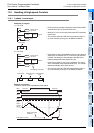
• If the operation of a high-speed counter is triggered by a device such as a switch, the counter may
malfunction due to extra noise from switch chattering or contact bounce.
• The input filter of an input terminal for a high-speed counter in the main unit is automatically set to 10 s
(X000, X001, X003, X004) or 50 s (X002, X005, X006, X007).
Accordingly, it is not necessary to use special data register D8020 (input filter adjustment).
The input filter for input relays not being used for high-speed counters remains at 10 ms (initial value).
• The inputs X000 to X007 are used for high-speed counters, input interrupt, pulse catch, SPD/DSZR/ZRN
instructions and general-purpose inputs. There should be no overlap between each input number.
• Make sure that the signal speed for high-speed counters does not exceed the response frequency
described above. If an input signal exceeds the response frequency, a WDT error may occur, or the
communication functions such as a parallel link may malfunction.
• The response frequency changes depending on the number of used counters, but the input filter value is
fixed to 10 s (X000, X001, X003, X004) or 50 s (X002, X005, X006, X007). Note that noise above the
response frequency may be counted depending on the filter value of the used input.
Counter No. Function switching method Details of change
C248(OP) • Reset input is not given.
C253(OP) • Reset input is not given.
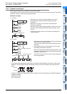
C254(OP)
• The input count (2-phase 2-count) changes as follows
Phase A : Changes from X000 to X006.
Phase B : Changes from X001 to X007.
• Reset input is not given.
• Start input is not given.
M8388
M8392
C248
K
M8388
M8392
C253
K
M8388
M8395
C254
K