


8 Installation In Enclosure
8.5 Procedures for Installing Directly (with M4 Screws)
113
FX3G Series Programmable Controllers
User's Manual - Hardware Edition
1
Introduction
2
Features and
Part Names
3
Product
Introduction
4
Specifications
5
Version and
Peripheral
Devices
6
System
Configuration
7
Input/Output
Nos., Unit Nos.
8
Installation
9
Preparation and
Power Supply
Wiring
10
Input Wiring
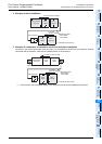
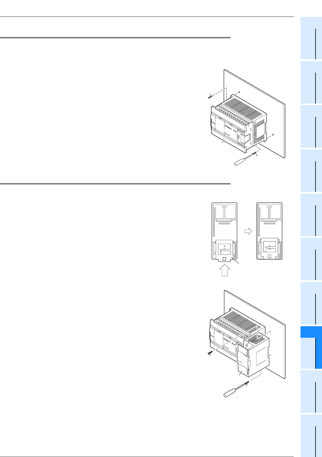
8.5.3 Installation of main unit
Mount the special adapters and connector conversion adapter (FX3G-CNV-ADP) on the main unit before
installing the unit in the enclosure.
→ For the connection procedure, refer to Subsection 8.6.3, Subsection 8.6.4.
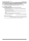
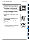
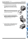
1 Make mounting holes in the mounting surface
according to the external dimensions diagram.
2 Fit the main unit (A in the right figure) based on
the holes, and secure it with M4 screws (B in the
right figure).
The positions and number of screws depend on the product.
Refer to the external dimensions diagram.
→ For the external dimensions, refer to Section 4.6.
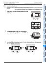
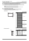
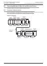
8.5.4 Installation of input/output powered extension unit/block and special function block
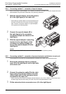
1 Make mounting holes in the mounting surface
according to the external dimensions diagram.
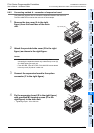
2 Push in the DIN rail mounting hook (A in the right
figure) of the input/output extension block.
If the DIN rail mounting hook is not pushed in, the screw hole is
covered, and the block cannot be mounted.
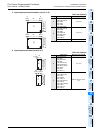
For input/output powered extension units, 8-point type input/
output extension blocks (except for the FX2N-8EYR-S-ES/UL)
and special function blocks, this operation is unnecessary.
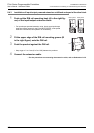
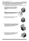
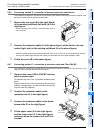
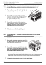
3 Fit the input/output extension block (B in the
right figure) based on the holes, and secure it
with M4 screws (C in the right figure).
The positions and number of screws depend on the product.
Refer to the external dimensions diagram.
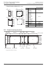
→ For the external dimensions of the input/output
powered extension unit, refer to Chapter 15.
→ For the external dimensions of the input/output
extension block, refer to Chapter 16.
→ For the external dimensions of the special function
blocks, refer to Chapter 18.
B
A
B
Rear panel Rear panel
2
A
B
C
C