


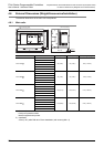
4 Specifications, External Dimensions and Terminal Layout (Main Units)
4.4 Output Specifications
48
FX3G Series Programmable Controllers
User's Manual - Hardware Edition
4.4 Output Specifications
The main unit output specifications are explained below.
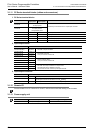
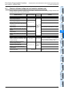
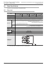
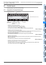
4.4.1 Relay output
*1. Each value inside ( ) indicates the number of occupied points.
Item
Relay output specifications
FX3G-14MR/ FX3G-24MR/ FX3G-40MR/ FX3G-60MR/
Number of output points
6 points(8)
*1
10 points(16)
*1
16 points 24 points
Connecting type Removable terminal block (M3 screw)
Output type Relay
External power supply
30V DC or less
240V AC or less(250V AC or less when the unit does not comply with CE, UL or cUL standards)
Max. load
Resistance
load
2A/point
The total load current of resistance loads per common terminal should be the following value.
→ For details on the common terminal for each model,
refer to the Section 4.7 Terminal Layout.
• 1 output point/common terminal: 2A or less
• 4 output points/common terminal: 8A or less
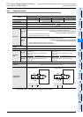
Inductive
load
80VA
→ For the product life, refer to Subsection 14.4.3.
→ For cautions on external wiring, refer to Subsection 12.1.4.
Min. load 5V DC, 2mA (reference value)
Open circuit leakage
current
-
Response
time
OFF ON Approx. 10ms
ON OFF Approx. 10ms
Circuit insulation Mechanical insulation
Display of output
operation
LED on panel lights when power is applied to relay coil.
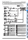
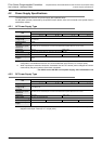
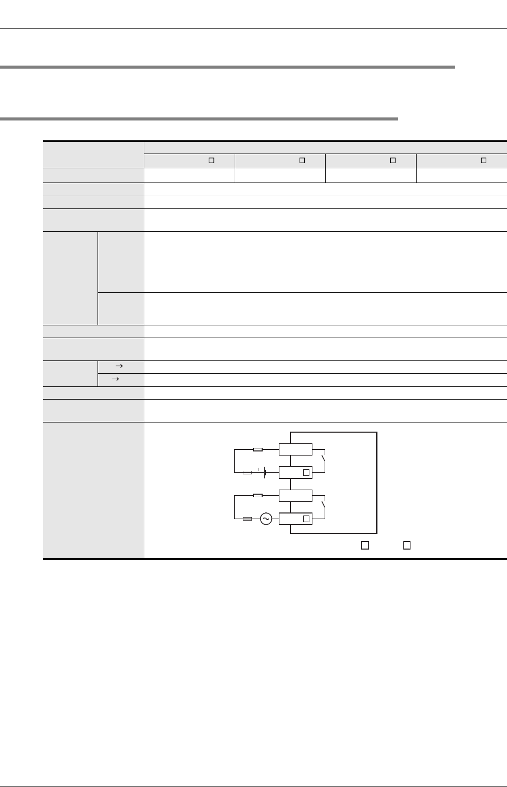
Output circuit
configuration
A
common number applies to the of [COM ].
AC power
supply
Load
Fuse
Y
COM
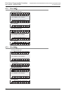
DC power
supply
Fuse
Y
COM
Load