


9 Preparation for Wiring and Power Supply Wiring Procedures
9.1 Preparation for Wiring
123
FX3G Series Programmable Controllers
User's Manual - Hardware Edition
1
Introduction
2
Features and
Part Names
3
Product
Introduction
4
Specifications
5
Version and
Peripheral
Devices
6
System
Configuration
7
Input/Output
Nos., Unit Nos.
8
Installation
9
Preparation and
Power Supply
Wiring
10
Input Wiring
9.1 Preparation for Wiring
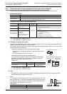
9.1.1 Wiring procedures
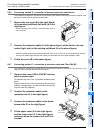
Before starting wiring work, make sure that the main power is off.
1 Prepare the parts for wiring.
Prepare the solderless terminals and cables necessary for wiring.
→ For details, refer to Section 9.2.
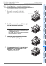
2 Wire the power supply terminals.
In the case of AC power supply type
• Connect the power supply to the terminals [L] and [N].
In the case of DC power supply type
• Connect the power supply to the terminals [ ] and [ ].
Provide the power supply circuit with the protection circuit shown in this subsection.
→ For details, refer to Section 9.4 and Section 9.5.
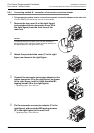
3 Wire the ground terminal [ ] at a grounding resistance of 100 or less
(Class D).
Connect a class D ground wire to the terminal.
→ For details, refer to Section 9.3 and Section 9.4.
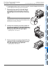
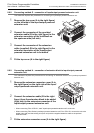
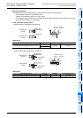
4 Wire the input [X] terminals.
For a type (24V DC input type) common to sink/source input, select sink or source input by the fol-
lowing connection.
In the case of AC power supply type
• For sink input, connect the [24V] and [S/S] terminals.
• For source input, connect the [0V] and [S/S] terminals.
In the case of DC power supply type
• For sink input, connect the [ ] and [S/S] terminals.
• For source input, connect the [ ] and [S/S] terminals.
Connect sensors and switches to the terminals.
→ For details, refer to Chapter 10.
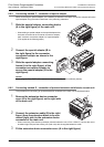
5 Wire the output [Y] terminals.
Connect loads to the terminals.
→ For details, refer to Chapter 12.
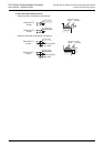
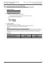
9.1.2 Removal and installation of quick-release terminal block
Removal Unscrew the terminal block mounting screws [both right and left screws] evenly, and remove the
terminal block.
Installation Place the terminal block in the specified position, and tighten the terminal block mounting screws
evenly [both right and left screws].
Tightening torque 0.4 to 0.5 N•m
Do not tighten the terminal block mounting screws with a torque outside the above-mentioned
range. Failure to do so may cause equipment failures or malfunctions.
*Pay attention so that the center of the terminal block is not lifted.