


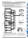

10 Input Wiring Procedures
10.1 Before Starting Input Wiring
141
FX3G Series Programmable Controllers
User's Manual - Hardware Edition
1
Introduction
2
Features and
Part Names
3
Product
Introduction
4
Specifications
5
Version and
Peripheral
Devices
6
System
Configuration
7
Input/Output
Nos., Unit Nos.
8
Installation
9
Preparation and
Power Supply
Wiring
10
Input Wiring
10.1 Before Starting Input Wiring
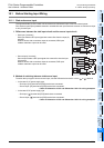
10.1.1 Sink and source input
The input terminals (X) of the main unit are common to sink/source input of 24V DC internal power.
FX
2N Series input/output powered extension units/blocks have input terminals common to sink/source input
or only for sink input.
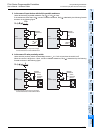
1. Differences between the sink input circuit and the source input circuit
• Sink input [-common]
Sink input means a DC input signal with current-flow from the input (X)
terminal.
When a sensor with a transistor output is connected, NPN open
collector transistor output can be used.
• Source input [+common]
Source input means a DC input signal with current-flow into the input
(X) terminal.
When a sensor with a transistor output is connected, PNP open
collector transistor output can be used.
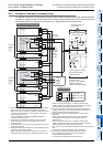
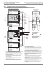
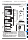
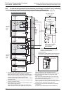
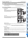
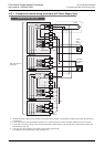
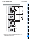
2. Method of switching between sink/source input
To switch the input type to sink or source input, wire the S/S terminal to the 0V or 24V ( or ) terminal.
• In the case of AC power supply type
- Sink input: [24V] terminal and [S/S] terminal are connected.
- Source input: [0V] terminal and [S/S] terminal are connected.
→ Refer to Subsection 10.2.3 and Subsection 10.2.4 for wiring examples.
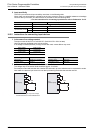
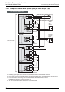
• In the case of DC power supply type
- Sink input: [ ] terminal and [S/S] terminal are connected.
- Source input: [ ] terminal and [S/S] terminal are connected.
→ Refer to Subsection 10.2.5 and Subsection 10.2.6 for wiring examples.
24V
N
L
X
S/S
0V
24V
N
L
X
S/S
0V