


6 Examination of System Configuration
6.1 Configuration of a Whole System
68
FX3G Series Programmable Controllers
User's Manual - Hardware Edition
6.1.1 Expansion board/connector conversion adapter/memory cassette/display module
configuration
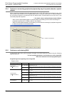
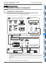
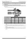
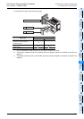
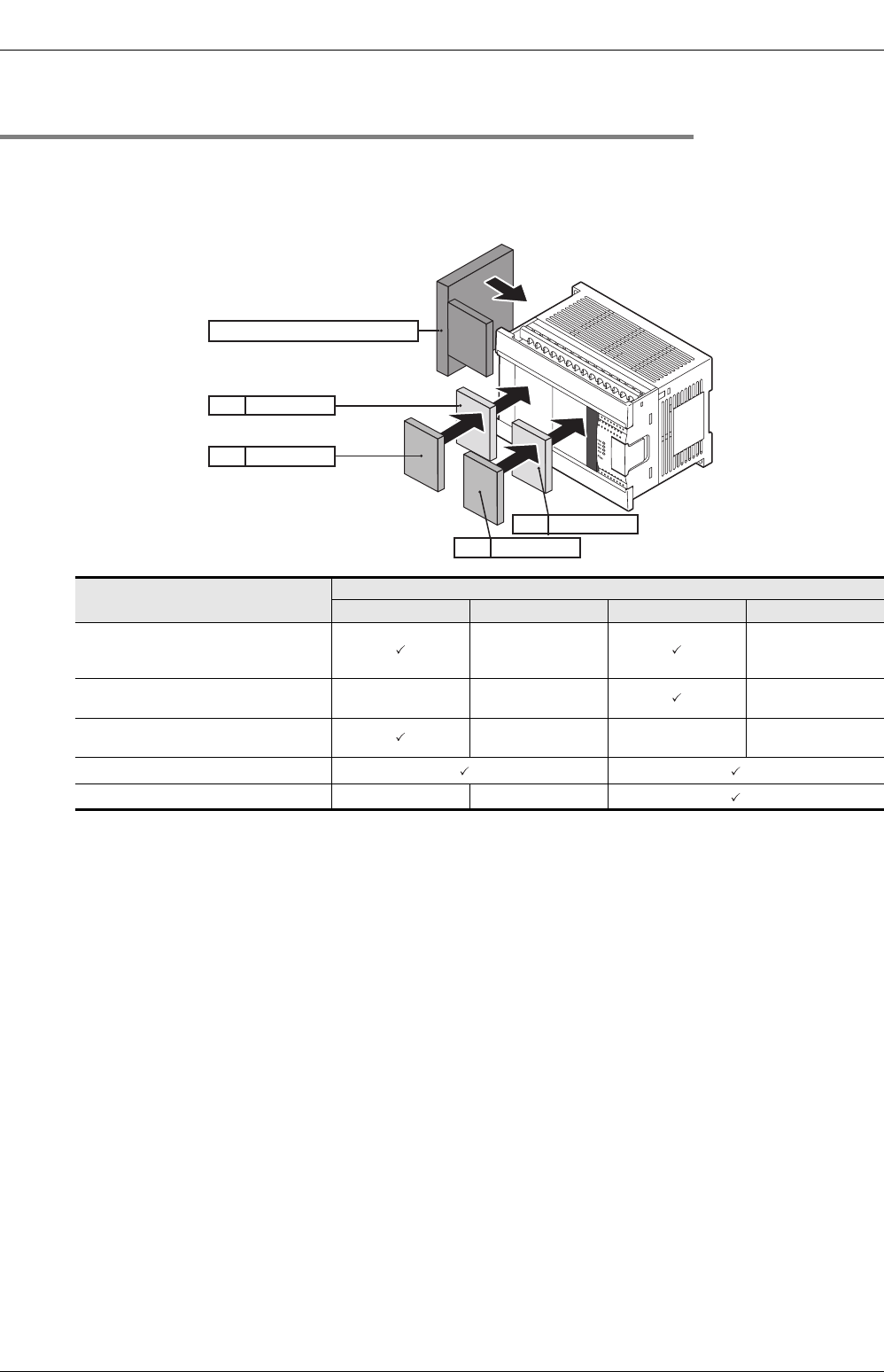
The connection positions and number of expansion boards, connector conversion adapter and memory
cassette configuration vary depending on the number of points in main units. For details, refer to the
description below.
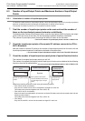
• In the case of the main units (40/60 point type)
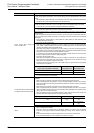
*1. When the memory cassette and display module are used together, the transfer function of the
memory cassette is not available. Use the display module to transfer data stored in the memory
cassette.
*2. Can be connected in any position however only one device can be connected at one time.
*3. The memory cassette cannot be connected when the display module is connected to the BD2 (1st
position).
*4. Only the BD2 (1st position) and the BD2 (2nd position) can be used for connection. Only one display
module can be connected to the main unit.
*5. The display module cannot be connected when the memory cassette is connected to the BD2 (1st
position).
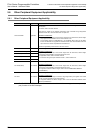
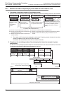
Model name
Available connection position
BD1 (1st position) BD1 (2nd position) BD2 (1st position) BD2 (2nd position)
Expansion board
(Except for the FX3G-4EX-BD,
FX3G-2EYT-BD, FX3G-8AV-BD)
--
FX3G-4EX-BD, FX3G-2EYT-BD,
FX3G-8AV-BD
-- -
Connector conversion adapter
(FX3G-CNV-ADP)
---
Memory cassette
*1 *2 *2*3
Display module
*1
--
*4*5
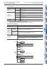
Connector conversion adapter
BD1 2nd position
BD1 1st position
BD2 2nd position
BD2 1st position