


6 Examination of System Configuration
6.2 Rules of System Configuration
71
FX3G Series Programmable Controllers
User's Manual - Hardware Edition
1
Introduction
2
Features and
Part Names
3
Product
Introduction
4
Specifications
5
Version and
Peripheral
Devices
6
System
Configuration
7
Input/Output
Nos., Unit Nos.
8
Installation
9
Preparation and
Power Supply
Wiring
10
Input Wiring
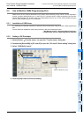
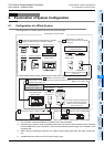
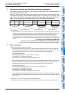
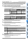
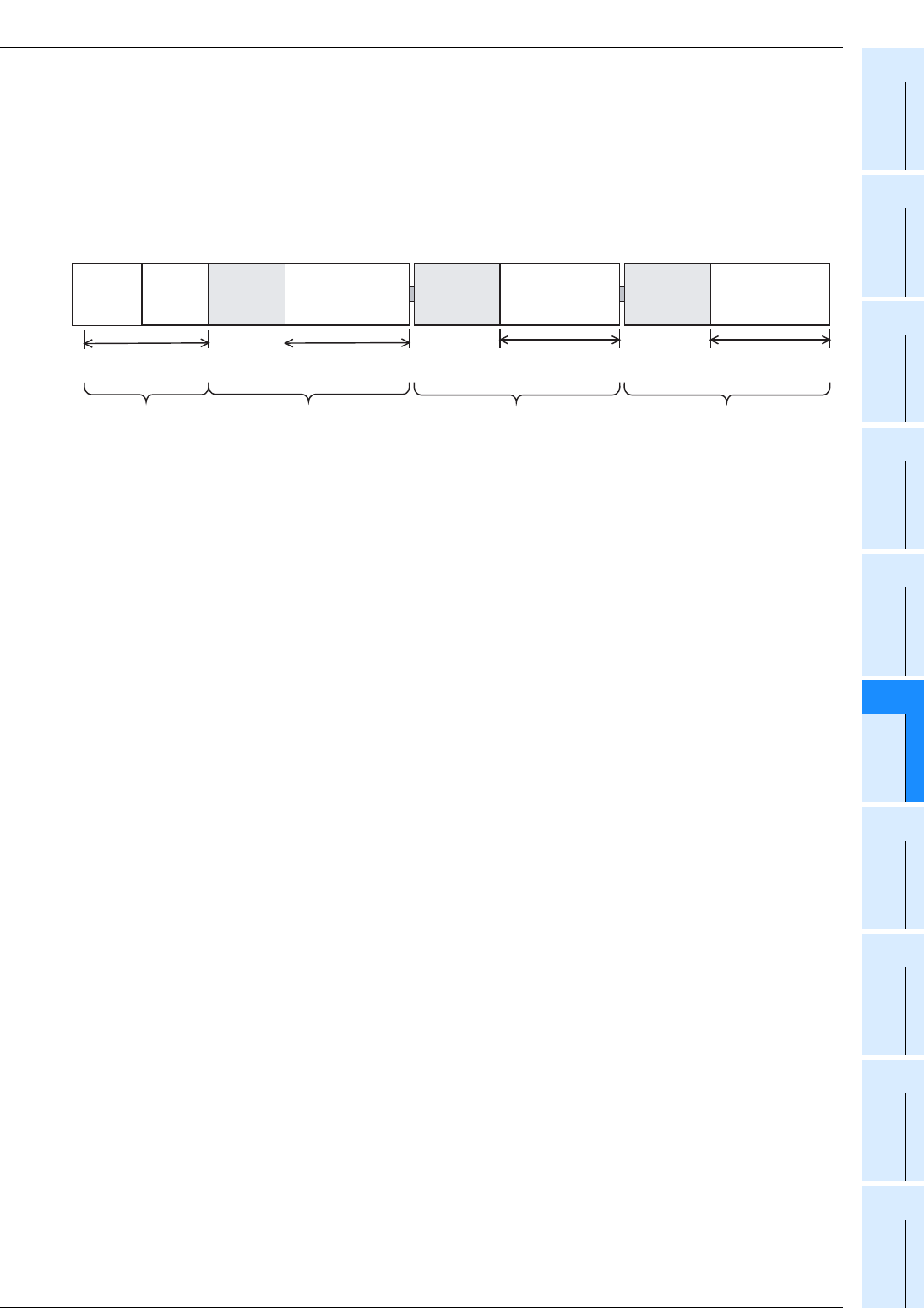
3 Connection restriction and calculation of current consumption
The number of points and number of units connected are restricted by the number of extension
blocks connected to the main unit.
The built-in power supply of the input/output powered extension unit and extension power supply
unit supplies the power to a unit/block/board extended to the corresponding unit. The built-in power
supply refers to the 24V DC service power supply, 5V DC power supply and internal 24V DC power
supply. The consumed power varies depending on the type of extended unit/block/board.
*1. When connecting an input extension block on the downstream side of an extension power supply unit,
supply the power to the input extension block from the nearest main unit on the upstream side, or from
an input/output powered extension unit on the upstream side of the extension power supply unit.
The extension power supply unit is available only when the main unit is a AC power supply type.
In the example above, the input/output powered extension unit supplies the power to extension
blocks.
→ For details, refer to 6.5 Expansion of Main Unit.
→ For details, refer to 6.6 Expansion of FX2N Series I/O Powered Extension Unit.
→ For details, refer to 6.7 Expansion of Extension Power Supply Unit (FX3U-1PSU-5V).
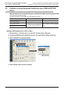
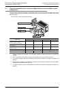
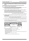
4 Other restrictions
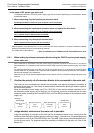
• Restrictions in the use of the FX3G-422-BD
- When connecting a device (such as GOT) which consumes an internal 5V DC to each of the RS-422
port built in the main unit and the FX
3G-422-BD at the same time, avoid continuous use of either device.
If both devices are used continuously, their life may be shortened due to heat generation.
<Configuration example 1>
RS-422 port built-in main unit + GT1020LBL (5V DC type)
FX
3G-422-BD + GT1020LBL (5V DC type)
Avoid continuous use of two GT1020LBL (5V DC type) units.
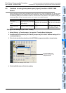
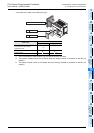
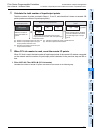
- When connecting a device (such as GOT) which consumes an internal 5V DC to each of two FX
3G-422-
BD units connected to the (40-point/60-point type) main unit, avoid continuous use of either device.
If both devices are used continuously, their life may be shortened due to heat generation.
<Configuration example 2>
When connecting the 40-point type main unit and two FX
3G-422-BD units
FX
3G-422-BD + GT1020LBL (5V DC type)
FX
3G-422-BD + GT1020LBL (5V DC type)
Avoid continuous use of two GT1020LBL (5V DC type) units.
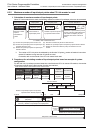
- It is not allowable to connect a device (such as GOT) which consumes an internal 5V DC to each of the
RS-422 port in the (40-point/60-point type) main unit and two FX
3G-422-BD units (3 channels in total) at
the same time.
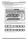
• Restrictions in the use of an input/output powered extension unit
When using an input/output extension unit, select a power supply type that is the same as the main unit.
Refer to Section 6.5. Refer to Section 6.6. Refer to Section 6.7.
Power supply from
input/output powered
extension unit
Power supply from
extension power
supply unit
*1
Power supply
from main unit
Extension block
(some blocks can
be connected)
Extension block
(some blocks can
be connected)
Extension block
(some blocks can
be connected)
Main unit
Input/output
powered
extension
unit
Extension
power supply
unit
Expansion
board
Special
adapter
Refer to Section 6.4.
Power supply
from main unit