


20 Terminal Block
20.8 FX-16EYT-TB, FX-16EYT-H-TB
371
FX3G Series Programmable Controllers
User's Manual - Hardware Edition
11
High-Speed
Counters
12
Output Wiring
13
Wiring for
Various Uses
14
Test Run,
Maintenance,
Troubleshooting
15
Input/Output
Powered
Extension Units
16
Input/Output
Extension
Blocks
17
Extension
Power Supply
Unit
18
Other Extension
Units and
Options
19
Display Module
20
Terminal Block
20.8.4 External wiring precautions
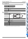
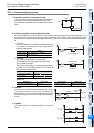
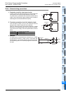
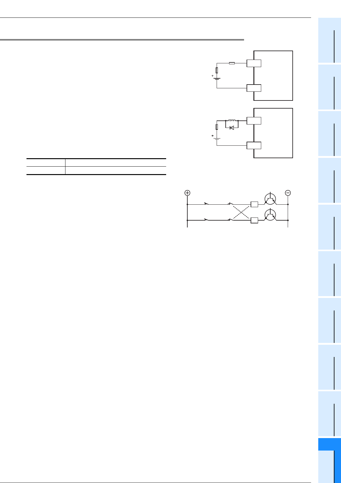
1. Protection circuit for load short-circuits
A short-circuit at a load connected to an output terminal
could cause burnout at the output element or the PCB.
To prevent this, a protection fuse should be inserted at the
output. Use a load power supply capacity that is at least 2
times larger than the total rated fuse capacity.
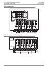
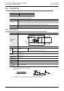
2. Transistor protection circuit for inductive loads
The transistor output circuit in the terminal block is
equipped with a Zener diode (50V) for protection.
When an inductive load is connected, however, a diode
should be connected parallel to the load when required.
The diode must comply with the specifications shown
below.
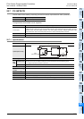
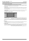
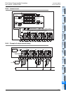
3. Interlock
For loads such as forward/reverse contactors, etc., where
a hazardous condition could result if switched ON
simultaneously, an external interlock should be provided
for interlocking the PLC's internal programs as shown to
the right.
Reverse voltage 5 to 10 times of the load voltage
Forward current Load current or more
Terminal block
0 to 7
COMn
Load
Fuse
Terminal block
0 to 7
COMn
inductive
load
Fuse
Forward
limit Interlock
Reverse
limit
PLC output
element
Forward
Reverse