


9 Preparation for Wiring and Power Supply Wiring Procedures
9.4 Examples of External Wiring [AC Power Supply Type]
133
FX3G Series Programmable Controllers
User's Manual - Hardware Edition
1
Introduction
2
Features and
Part Names
3
Product
Introduction
4
Specifications
5
Version and
Peripheral
Devices
6
System
Configuration
7
Input/Output
Nos., Unit Nos.
8
Installation
9
Preparation and
Power Supply
Wiring
10
Input Wiring
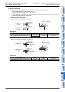
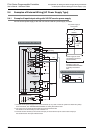
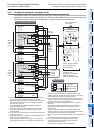
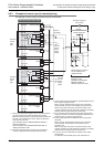
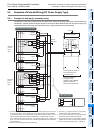
9.4.2 Example of sink input [-common] wiring
An example of sink input [-common] wiring is given below. When connecting input/output powered extension
units/blocks, carefully check the signal names on the terminal block because the sink and source input type
units/blocks and the sink input type units/blocks vary in signal names on the terminal block.
AC power supply of
100 to 240V
*1 Connect the AC power supply to the L and N terminals (in
any case of 100V AC system and 200V AC system).
Make sure that the power is turned ON at the same time in
the main unit and extension units or earlier in extension
units than the main unit.
As for the details, see "WIRING PRECAUTIONS" at
"Safety Precautions" field.
Connect the 24V terminal of the main unit or the input/
output extension unit to the S/S terminal of the input
extension block.
*2
In the case of the sink input type, the S/S terminal is used
as the 24+ terminal.
*3
Do not connect the 24V terminals (24V DC service power
supply) of the main unit and the input/output extension unit
with each other. Connect the 0V terminal.
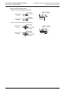
*5
Some special extension units/blocks do not have power
terminals.
When using an external power supply, turn it ON at the
same time with the extension unit or earlier than the
extension unit.
When turning OFF the power, confirm the safety of the
system, and then turn OFF the power of the PLC (including
special extension equipment) at the same time.
*6
The "24V" and "0V" terminals are located on the output terminal
side.
For details on the terminal layout, refer to Section 4.7.
*7
When turning OFF the power, confirm the safety of the
system, and then turn OFF the power of the PLC (including
special extension equipment) at the same time.
S/S
L
N
0V
Special adapter
24-
24+
PL
Power supply ON
Emergency
stop
MC
MC
MC MC
DC
power
supply
Power supply for loads to
be connected to PLC
output terminals
As for the details of
emergency stop
operation, see "DESIGN
PRECAUTIONS" at
"Safety Precautions" field.
24V
Main unit
Input extension
block
S/S
24V DC
service
power
supply
output
Class D
grounding
DC AC
*5
*1
Sink and source input type
*2,
*
3
5V 0V 24V
5V 0V 24V
5V 0V 24V
Sink and
source
input
type
Breaker
24-
24+
*4
Special function
block
5V 0V 24V
S/S
L
N
0V
24V
S/S
24-
24+
24V DC
service
power
supply
output
*5
(C)(B)(A)
*1
*2,*3
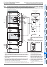
Sink input type
COM
24+
*8
24V DC
service power
supply output
Input / output powered extension unit
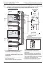
5V 0V 24V
5V 0V 24V
Input extension
block
Special function
block
5V 0V 24V
5V 0V 24V
Output extension
block
Sink and
source
input
type
*7
*7
*6
(C)(B)(A)
Do not connect the 24V terminal of the main unit to
the 24+ terminal (24V DC service power supply) of
an input/output extension unit.
Connect the 0V terminal to the COM terminal.
*8
Some special function units/blocks, special adapter do not
have the power supply terminal.
When using an external power supply, turn it ON at the
same time with the main unit or earlier than the main unit.
*4
*4