


2 Features and Part Names
2.2 Names and Functions of Parts
31
FX3G Series Programmable Controllers
User's Manual - Hardware Edition
1
Introduction
2
Features and
Part Names
3
Product
Introduction
4
Specifications
5
Version and
Peripheral
Devices
6
System
Configuration
7
Input/Output
Nos., Unit Nos.
8
Installation
9
Preparation and
Power Supply
Wiring
10
Input Wiring
2.2 Names and Functions of Parts
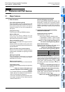
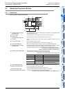
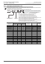
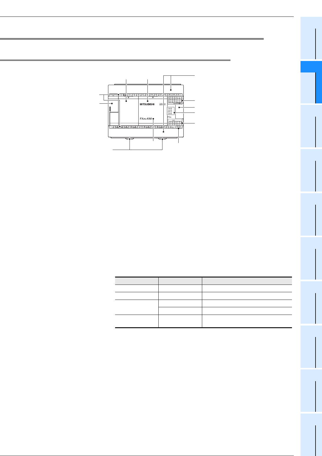
2.2.1 Front Panel
Factory default configuration (standard)
[1] Peripheral device connecting
connector cover
The peripheral device connector, variable analog potentiometers and RUN/STOP switch
are located under this cover.
[2] Terminal names The signal names for power supply, input and output terminals are shown.
[3] Top cover (S)
(40points, 60points type only)
Mount the expansion board and memory cassette under this cover.
[4] Top cover Mount the expansion board, display module, memory cassette and battery under this
cover.
[5] Terminal block covers The covers can be opened for wiring.
Keep the covers closed while the PLC is running (the unit power is on).
[6] Input display LEDs (red) When an input terminal (X000 or more) is turned on, the corresponding LED lights.
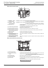
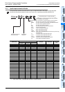
[7] Extension device connecting
connector cover
Connect the extension cables of input/output powered extension unit/block or special
function block to the extension device connecting connectors under this cover.
FX3U Series extension devices and FX2N Series extension devices can be connected.
→ For details on the extension devices, refer to
Chapter 15, Chapter 16, Chapter 17 and Section 18.1.
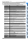
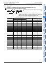
[8] Operation status display LEDs The operation status of the PLC can be checked with the LEDs.
The LEDs turn off, light and flash according to the following table.
→ For details on the operation status, refer to Section 14.5.
[9] Output display LEDs (red) When an output terminal (Y000 or more) is turned on, the corresponding LED lights.
[10] Model name (abbreviation) The model name of the main unit is indicated.
Check the nameplate on the right side for the model name.
[11] DIN rail mounting hooks The main unit can be installed on DIN46277 rail (35mm (1.38") wide).
[12] The year and month of production The year and month of production of the main unit is indicated.
→
For details on the year and month of production, refer to Subsection 5.1.2
.
[6]
[2]
[1]
[5]
[4][3]
[9]
[11]
[8]
[7]
[10]
[12]
LED name Display color Description
POW Green On while power is on the PLC.
RUN Green On while the PLC is running.
ERR
Red Flashing when a program error occurs.
Red Lights when a CPU error occurs.
ALM Red
Lights when the battery voltage drops.
(When the optional battery is used)