


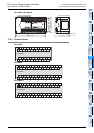

16 Input/Output Extension Blocks
245
FX3G Series Programmable Controllers
User's Manual - Hardware Edition
11
High-Speed
Counters
12
Output Wiring
13
Wiring for
Various Uses
14
Test Run,
Maintenance,
Troubleshooting
15
Input/Output
Powered
Extension Units
16
Input/Output
Extension
Blocks
17
Extension
Power Supply
Unit
18
Other Extension
Units and
Options
19
Display Module
20
Terminal Block
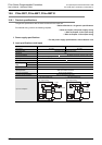
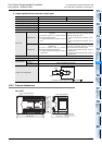
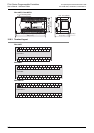
16. Input/Output Extension Blocks
DESIGN PRECAUTIONS
• Make sure to have the following safety circuits outside of the PLC to ensure safe system operation even during external power supply
problems or PLC failure.
Otherwise, malfunctions may cause serious accidents.
1) Most importantly, have the following: an emergency stop circuit, a protection circuit, an interlock circuit for opposite movements
(such as normal vs. reverse rotation), and an interlock circuit (to prevent damage to the equipment at the upper and lower
positioning limits).
2) Note that when the PLC CPU detects an error, such as a watchdog timer error, during self-diagnosis, all outputs are turned off.
Also, when an error that cannot be detected by the PLC CPU occurs in an input/output control block, output control may be
disabled.
External circuits and mechanisms should be designed to ensure safe machinery operation in such a case.
3) Note that the output current of the 24V DC service power supply varies depending on the model and the absence/presence of
extension blocks. If an overload occurs, the voltage automatically drops, inputs in the PLC are disabled, and all outputs are turned
off.
External circuits and mechanisms should be designed to ensure safe machinery operation in such a case.
4) Note that when an error occurs in a relay, triac or transistor output device, the output could be held either on or off.
For output signals that may lead to serious accidents, external circuits and mechanisms should be designed to ensure safe
machinery operation in such a case.
DESIGN PRECAUTIONS
• Do not bundle the control line together with or lay it close to the main circuit or power line. As a guideline, lay the control line at least
100mm (3.94") or more away from the main circuit or power line.
Noise may cause malfunctions.
WIRING PRECAUTIONS
• Make sure to cut off all phases of the power supply externally before attempting installation or wiring work.
Failure to do so may cause electric shock or damage to the product.
• Make sure to attach the terminal cover, offered as an accessory, before turning on the power or initiating operation after installation or
wiring work.
Failure to do so may cause electric shock.
WIRING PRECAUTIONS
• Connect the AC power supply wiring to the dedicated terminals described in this manual.
If an AC power supply is connected to a DC input/output terminal or DC power supply terminal, the PLC will burn out.
• Connect the DC power supply wiring to the dedicated terminals described in this manual.
If an AC power supply is connected to a DC input/output terminal or DC power supply terminal, the PLC will burn out.
• Do not wire vacant terminals externally.
Doing so may damage the product.
• When drilling screw holes or wiring, make sure cutting or wire debris does not enter the ventilation slits.
Failure to do so may cause fire, equipment failures or malfunctions.
• Make sure to properly wire the FX
3G Series main unit and FX2N/FX3U Series extension equipment in accordance with the following
precautions.
Failure to do so may cause electric shock, equipment failures, a short-circuit, wire breakage, malfunctions, or damage to the product.
- The disposal size of the cable end should follow the dimensions described in the manual.
- Tightening torque should follow the specifications in the manual.
- Tighten the screws using a Phillips-head screwdriver No.2 (shaft diameter 6mm (0.24") or less). Make sure that the screwdriver
does not touch the partition part of the terminal block.