8 Installation In Enclosure
8.5 Procedures for Installing Directly (with M4 Screws)
111
FX3G Series Programmable Controllers
User's Manual - Hardware Edition
1
Introduction
2
Features and
Part Names
3
Product
Introduction
4
Specifications
5
Version and
Peripheral
Devices
6
System
Configuration
7
Input/Output
Nos., Unit Nos.
8
Installation
9
Preparation and
Power Supply
Wiring
10
Input Wiring
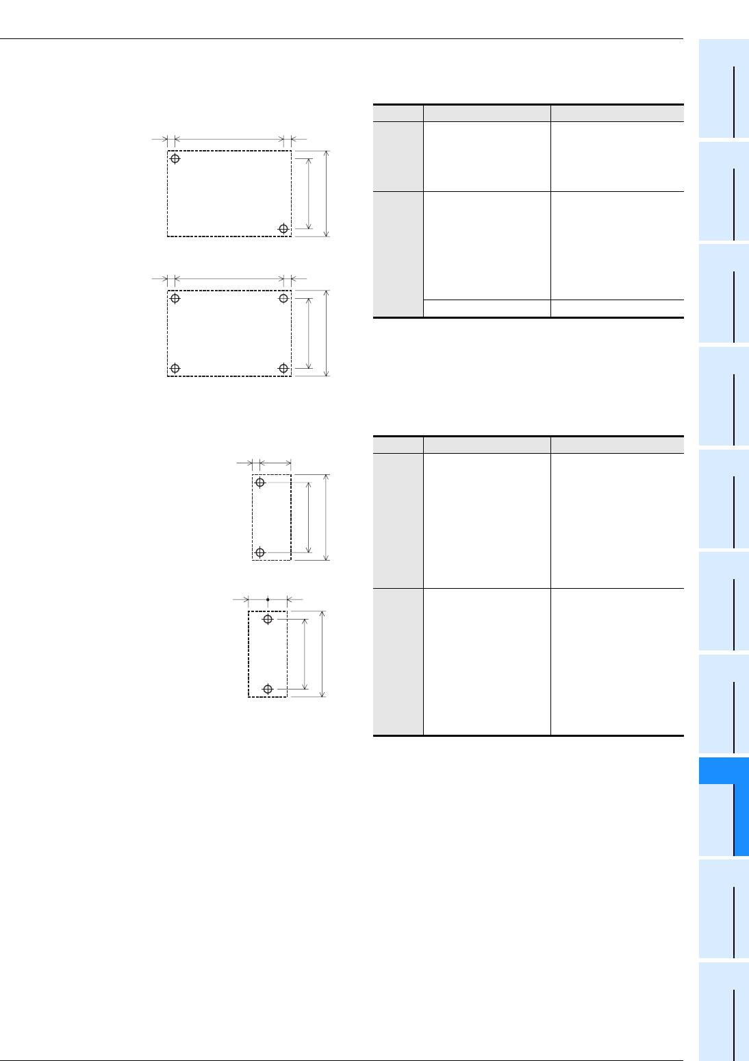
3. Input/output powered extension unit (C or D)
Unit: mm (inches)
4. Input/output extension block (E or F)
Unit: mm (inches)
Model name Mounting hole pitch(W)
C
FX2N-32ER-ES/UL
FX2N-32ET-ESS/UL
FX2N-32ER
FX2N-32ET
FX2N-32ES
140 (5.52")
D
FX2N-48ER-ES/UL
FX2N-48ET-ESS/UL
FX2N-48ER
FX2N-48ET
FX2N-48ER-DS
FX2N-48ET-DSS
FX2N-48ER-D
FX2N-48ET-D
172 (6.78")
FX2N-48ER-UA1/UL 210 (8.27")
Model name Mounting hole pitch(W)
E
FX2N-8ER-ES/UL
FX2N-8ER
FX2N-8EX-ES/UL
FX2N-8EX
FX2N-8EX-UA1/UL
FX2N-8EYR-ES/UL
FX2N-8EYT-ESS/UL
FX2N-8EYR
FX2N-8EYT
FX2N-8EYT-H
39 (1.54")
F
FX
2N-8EYR-S-ES/UL
FX2N-16EX-ES/UL
FX2N-16EX
FX
2N-16EX-C
FX
2N-16EXL-C
FX
2N-16EYR-ES/UL
FX2N-16EYR
FX
2N-16EYT-ESS/UL
FX
2N-16EYT
FX2N-16EYT-C
FX
2N-16EYS
Refer to the figure shown
left.
5
(0.2")
C
W
80 (3.15")
90 (3.55")
D
W
80 (3.15")
90 (3.55")
5
(0.2")
5
(0.2")
5
(0.2")
4
(0.16")
W
80 (3.15")
E
90 (3.55")
F
20
(0.87")
20
(0.87")
80 (3.15")
90 (3.55")


