


9 Preparation for Wiring and Power Supply Wiring Procedures
9.5 Examples of External Wiring [DC Power Supply Type]
138
FX3G Series Programmable Controllers
User's Manual - Hardware Edition
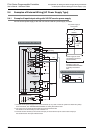
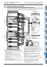
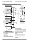
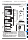
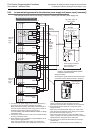
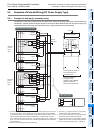
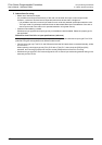
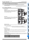
9.5.2 Example of source input [+common] wiring
An example of source input [+common] wiring is shown below.
*1 *2
*3
*4
Special adapter
24-
24+
PL
Power supply ON
Emergency
stop
MC
MC
S/S
*3
5V 0V 24V
5V 0V 24V
MC MC
24-
24+
*1, *4
*1, *4
5V 0V 24V
S/S
24-
24+
*1, *4
*1
*3
5V 0V 24V
5V 0V 24V
5V 0V 24V
24V DC
Circuit protector
*2
S/S
Main unit
*1
5V 0V 24V
S/S
0V
24V
Input/output powered extension unit
5V 0V 24V
Sink and
source
input
type
Sink and
source
input
type
As for the details of
emergency stop
operation, see "DESIGN
PRECAUTIONS" at
"Safety Precautions" field.
Connect DC power to [+] and [-] terminals. The same power
source for the main unit, extension units, special function
unit/blocks and special adapters is preferable. When using the
different power source from the main unit, turn ON the
peripheral devices' power simultaneously, or earlier than
the main unit's. When turning OFF the power, confirm the
safety of the system, and then turn OFF the power of the
PLC (including special extension equipment) at the same time.
Do not connect with [0V] and [24V]
terminals.
24V DC [-] supplies power to the [S/S]
terminal at the input extension block.
Some special function units/blocks, special
adapters do
not have a power supply terminal.
Output extension
block
Special function
block
Input extension
block
Special function
block
Input extension
block
Class D
grounding
Power supply for loads to
be connected to PLC
output terminals
Sink and source input type