


12 Output Wiring Procedures
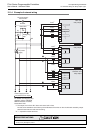
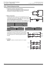
12.2 External Wiring of Transistor Output (Sink/Source) Type
180
FX3G Series Programmable Controllers
User's Manual - Hardware Edition
7. Open circuit leakage current
0.1mA or less
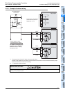
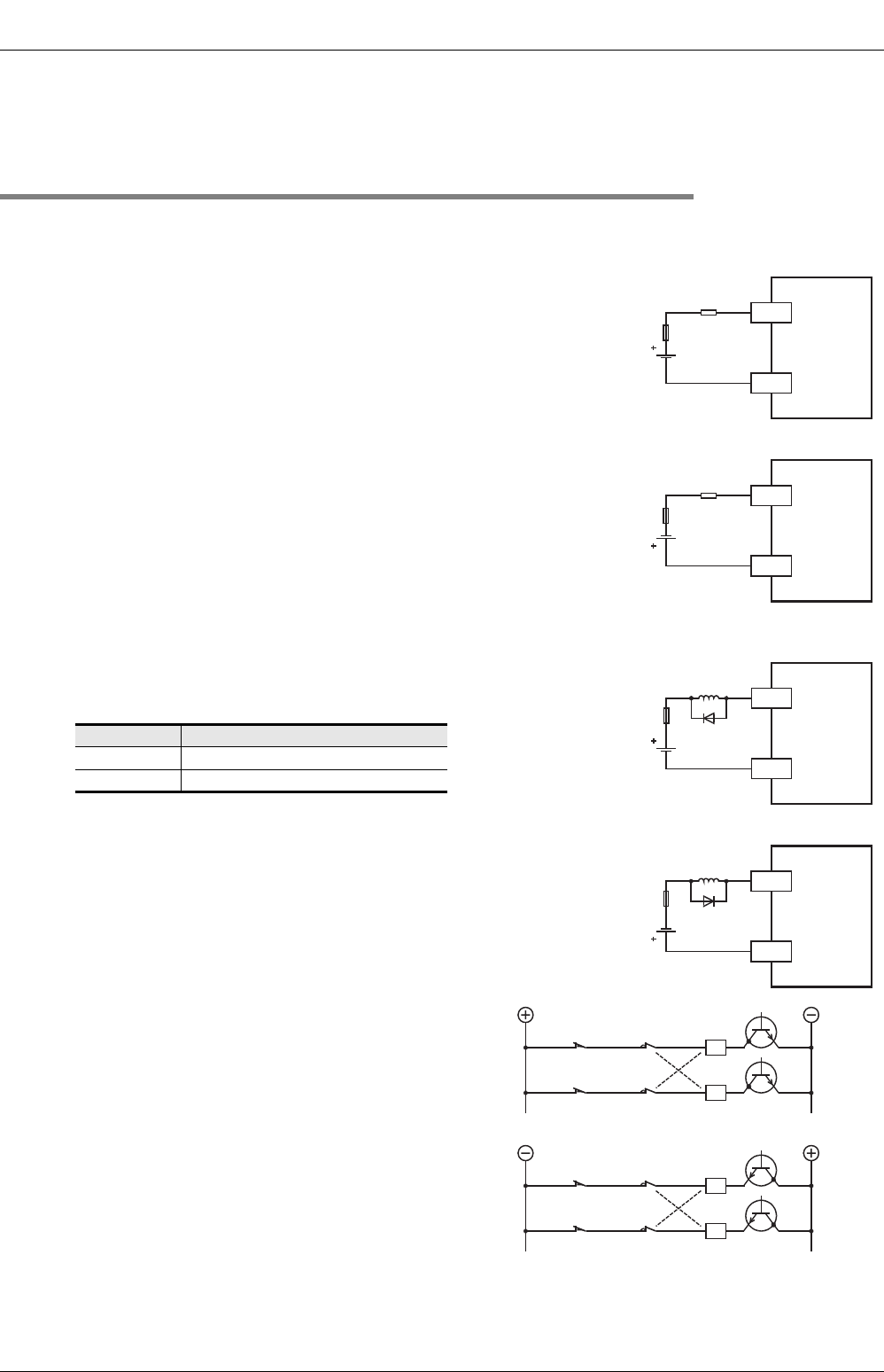
12.2.3 External wiring precautions
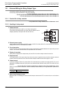
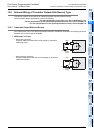
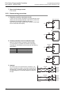
1. Protection circuit for load short-circuits
A short-circuit at a load connected to an output terminal could
cause burnout at the output element or the PCB. To prevent this,
a protection fuse should be inserted at the output.
Use a load power supply capacity that is at least 2 times larger
than the total rated fuse capacity.
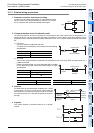
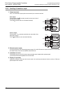
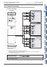
2. Contact protection circuit for inductive loads
When an inductive load is connected, connect a diode
(for commutation) in parallel with the load as necessary.
The diode (for commutation) must comply with the following
specifications.
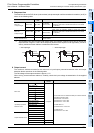
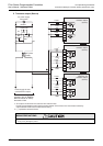
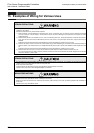
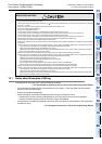
3. Interlock
For loads such as forward/reverse contactors, etc.,
where a hazardous condition could result if switched ON
simultaneously, an external interlock should be provided
for interlocking the PLC's internal programs, as shown to
the right.
Item Guide
Reverse voltage 5 to 10 times of the load voltage
Forward current Load current or more
PLC
Y
COM1
Load
Fuse
Sink output type
PLC
Y
+V0
Load
Fuse
Source output type
PLC
Y
COM1
Inductive
load
Fuse
Sink output type
PLC
Y
+V0
Inductive
load
Fuse
Source output type
Limit of normal
rotation
Interlock
Limit of reverse
rotation
PLC output
element
Normal
rotation
Reverse
rotation
Limit of normal
rotation
Interlock
Limit of reverse
rotation
PLC output
element
Normal
rotation
Reverse
rotation