


16 Input/Output Extension Blocks
251
FX3G Series Programmable Controllers
User's Manual - Hardware Edition
11
High-Speed
Counters
12
Output Wiring
13
Wiring for
Various Uses
14
Test Run,
Maintenance,
Troubleshooting
15
Input/Output
Powered
Extension Units
16
Input/Output
Extension
Blocks
17
Extension
Power Supply
Unit
18
Other Extension
Units and
Options
19
Display Module
20
Terminal Block
16.3 FX2N-8ER (24V DC Sink Input, Relay Output)
16.3 FX2N-8ER (24V DC Sink Input, Relay Output)
16.3.1 Product specifications
The generic specifications are identical to the main unit specifications.
→ Refer to Section 4.1 for generic specifications.
For external wiring, refer to the following chapters.
→ Refer to Chapter 10 for input wiring.
→ Refer to Chapter 12 for output wiring.
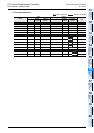
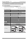
1. Power supply specifications
2. Weight and Other specifications (External dimensions are described later.)
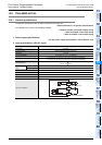
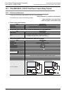
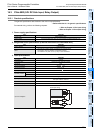
3. Input specifications
Item FX2N-8ER
Product type FX2N extension block
Rated voltage 24V DC (supplied from main unit and input/output powered extension unit)
Item FX2N-8ER
MASS (Weight) 0.2kg (0.44lbs)
Other
• The extension cable is already connected to the extension block.
• Accessories: Label for indication of input/output number
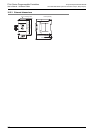
• The DIN46277 rail (width: 35 mm (1.38")) or direct installation.
Item FX2N-8ER
Input points 4 points
Connection type Vertical terminal block (M3 screws)
Input form Sink
Input signal voltage 24V DC 10%
Input signal current 5mA/24V DC
Input impedance
4.3k
ON input
sensitivity current
Input ON current 3.5mA or more at 24V DC
Input OFF current 1.5mA or less
Input response time Approx. 10ms
Input signal form
No-voltage contact input
NPN open collector transistor
Input circuit insulation Photo-coupler insulation
Indication of input operation LED on panel lights when input.
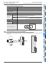
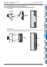
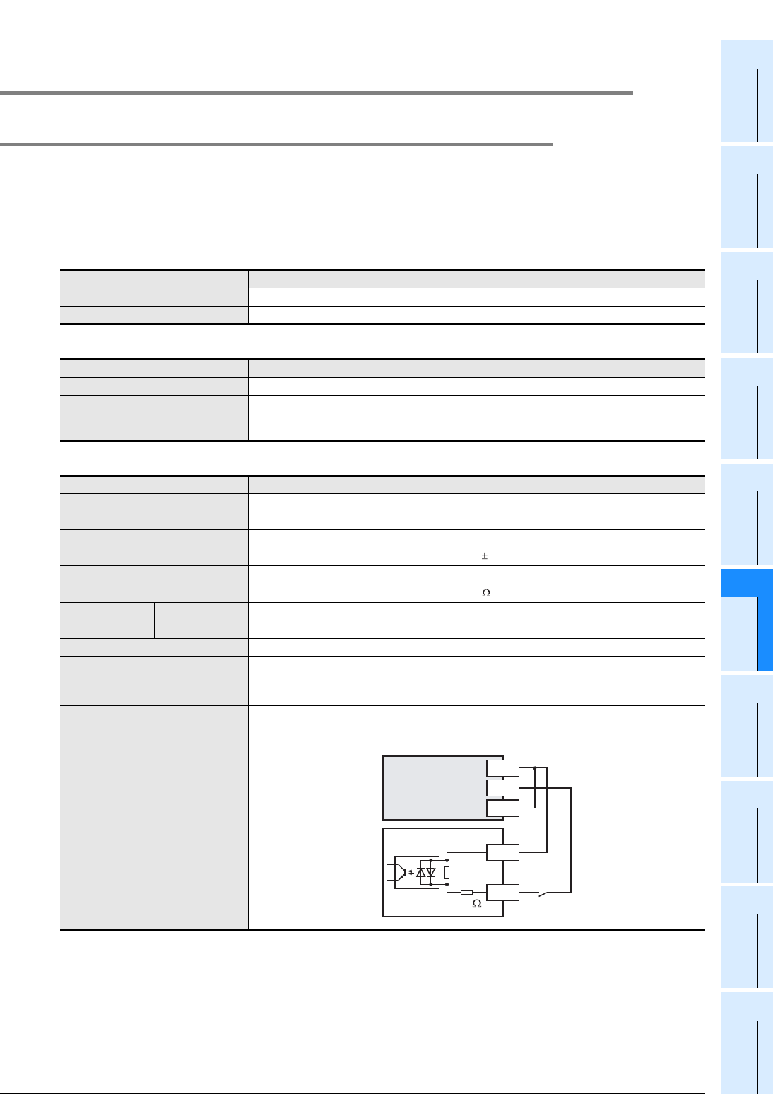
Input circuit diagram
X
24+
4.3k
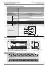
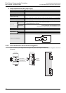
Sink input wiring
Main unit
24V
S/S
0V