


12 Output Wiring Procedures
12.2 External Wiring of Transistor Output (Sink/Source) Type
179
FX3G Series Programmable Controllers
User's Manual - Hardware Edition
11
High-Speed
Counters
12
Output Wiring
13
Wiring for
Various Uses
14
Test Run,
Maintenance,
Troubleshooting
15
Input/Output
Powered
Extension Units
16
Input/Output
Extension
Blocks
17
Extension
Power Supply
Unit
18
Other Extension
Units and
Options
19
Display Module
20
Terminal Block
5. Response time
The time from when the PLC drives (or shuts down) the photocoupler until the transistor is turned on (or off) is
shown in the following table.
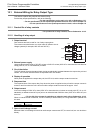
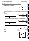
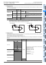
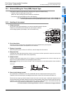
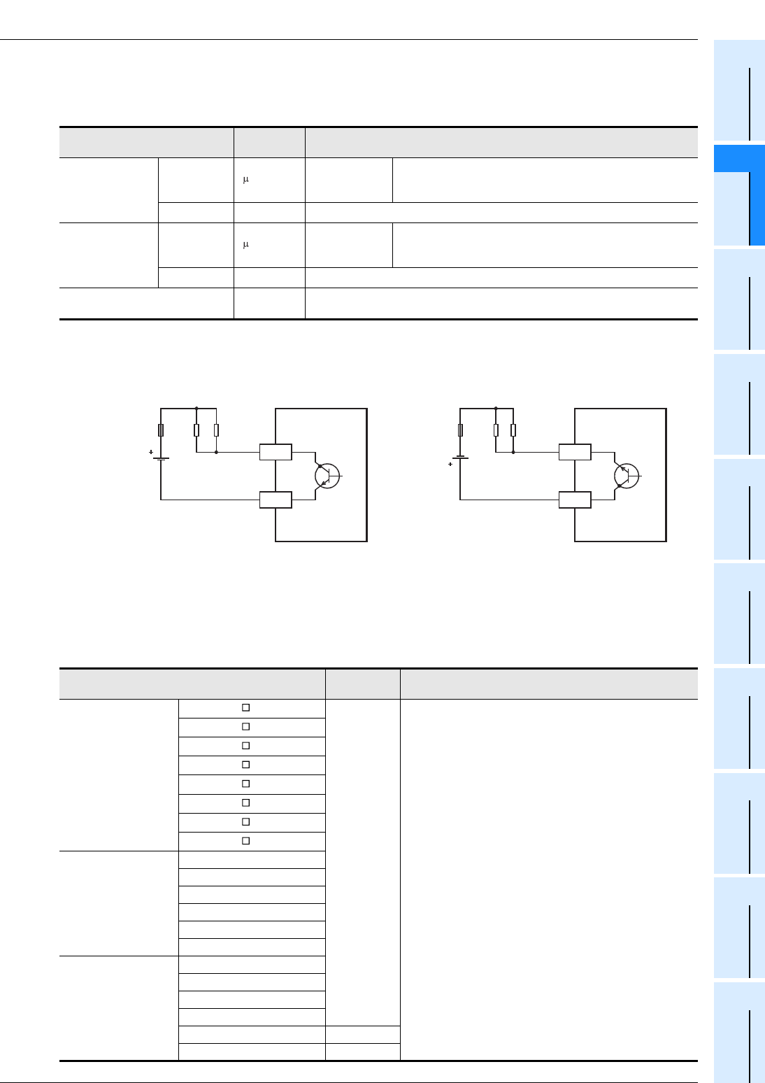
*1. The transistor OFF time is longer under lighter loads. For example, under a load of 24V DC 40mA, the
response time is approx. 0.3ms. When response performance is required under light loads, provide a
dummy resistor as shown below to increase the load current.
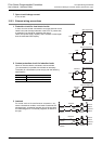
6. Output current
The maximum resistance loads for the main unit or input/output powered extension units and output
extension blocks are shown in the following table.
The ON voltage of the output transistor is approx. 1.5V.
When driving a semiconductor element, carefully check the input voltage characteristics of the applied
element.
Classification
Response
time
Load current
Main unit
14/24 point type
Y000, Y001 5 s or less
5 to 24V DC
10mA or more
When using an instruction related to pulse train output or
positioning, make sure to set the load current to 10 to 100mA
(5 to 24V DC).
Y002 or more 0.2ms or less
24V DC 200 mA or more
*1
Main unit
40/60 point type
Y000 to Y002 5 s or less
5 to 24V DC
10mA or more
When using an instruction related to pulse train output or
positioning, make sure to set the load current to 10 to 100mA
(5 to 24V DC).
Y003 or more 0.2ms or less
24V DC 200mA or more
*1
Input/output powered extension unit
Output extension block
0.2ms or less
24V DC 200mA
*1
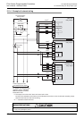
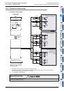
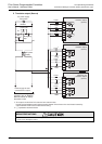
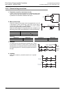
• Sink output type • Source output type
Model
Output
current
Limitation
Main units
FX
3G-14MT/ S
0.5A/point
The total load current of resistance loads per common terminal
should be the following value.
1 point/common: 0.5A or less
4 points/common: 0.8A or less
8 points/common: 1.6A or less
For FX
2N-16EYT-C:
16 points/common: 1.6A or less
For FX2N-8EYT-H:
4 points/common: 2A or less
FX
3G-14MT/ SS
FX3G-24MT/ S
FX3G-24MT/ SS
FX
3G-40MT/ S
FX3G-40MT/ SS
FX3G-60MT/ S
FX3G-60MT/ SS
Input/output powered
extension units
FX2N-32ET-ESS/UL
FX2N-48ET-ESS/UL
FX2N-48ET-DSS
FX2N-32ET
FX2N-48ET
FX
2N-48ET-D
Output extension block
FX
2N-16EYT-ESS/UL
FX2N-8EYT-ESS/UL
FX
2N-16EYT
FX
2N-8EYT
FX2N-8EYT-H 1A/point
FX2N-16EYT-C 0.3A/point
PLC
Y
COM1
Dummy
resistance
Load
Fuse
PLC
Y
+V0
Dummy
resistance
Load
Fuse