


4 Specifications, External Dimensions and Terminal Layout (Main Units)
4.4 Output Specifications
49
FX3G Series Programmable Controllers
User's Manual - Hardware Edition
1
Introduction
2
Features and
Part Names
3
Product
Introduction
4
Specifications
5
Version and
Peripheral
Devices
6
System
Configuration
7
Input/Output
Nos., Unit Nos.
8
Installation
9
Preparation and
Power Supply
Wiring
10
Input Wiring
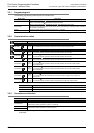
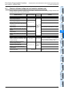
4.4.2 Transistor output
*1. Each value inside ( ) indicates the number of occupied points.
Item
Transistor output specifications
FX3G-14MT/ FX3G-24MT/ FX3G-40MT/ FX3G-60MT/
Number of output points
6 points(8)
*1
10 points(16)
*1
16 points 24 points
Connecting type Removable terminal block (M3 screw)
Output type/form
Transistor/sink output (FX3G-MT/S)
Transistor/source output (FX3G- MT/ SS)
External power supply 5 to 30V DC
Max. load
Resistance
load
0.5A/point
The total load current of resistance loads per common terminal should be the following value.
→ For details on the common terminal for each model,
refer to the Section 4.7 Terminal Layout.
• 1 output point/common terminal: 0.5A or less
• 4 output points/common terminal: 0.8A or less
Inductive
load
12W/24V DC
The total of inductive loads per common terminal should be the following value.
→ For details on the common terminal for each model,
refer to the Section 4.7 Terminal Layout.
• 1 output point/common terminal: 12W or less/24V DC
• 4 output points/common terminal: 19.2W or less/24V DC
Open circuit leakage
current
0.1mA or less/30V DC
ON voltage 1.5 V or less
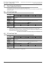
Response
time
OFF ON
Y000, Y001:5 s or less/10mA or more
(5 to 24V DC)
Y002 or more:0.2ms or less/200mA or more
(at 24V DC)
Y000 to Y002:5 s or less/10mA or more
(5 to 24V DC)
Y003 or more:0.2ms or less/200mA or more
(at 24V DC)
ON OFF
Y000, Y001:5 s or less/10mA or more
(5 to 24V DC)
Y002 or more:0.2ms or less/200mA or more
(at 24V DC)
Y000 to Y002:5 s or less/10mA or more
(5 to 24V DC)
Y003 or more:0.2ms or less/200mA or more
(at 24V DC)
Circuit insulation Photocoupler insulation
Display of output
operation
LED on panel lights when photocoupler is driven.
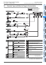
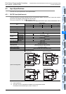
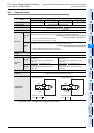
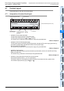
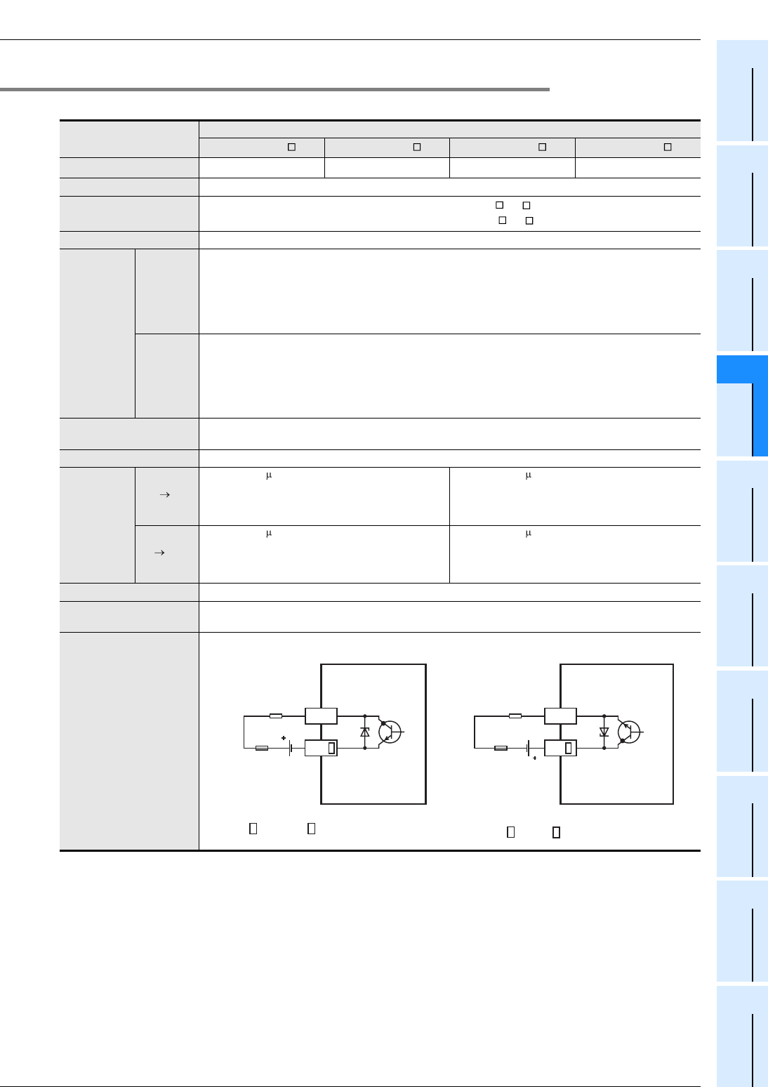
Output circuit
configuration
Load
Fuse
DC power
supply
Y
COM
A common number applies
to the of [COM ].
Sink output wiring
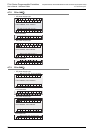
Load
Fuse
DC power
supply
Y
+V
A common number applies
to the of [+V ].
Source output wiring