


8 Installation In Enclosure
8.4 Procedures for Installing on and Detaching from DIN Rail
109
FX3G Series Programmable Controllers
User's Manual - Hardware Edition
1
Introduction
2
Features and
Part Names
3
Product
Introduction
4
Specifications
5
Version and
Peripheral
Devices
6
System
Configuration
7
Input/Output
Nos., Unit Nos.
8
Installation
9
Preparation and
Power Supply
Wiring
10
Input Wiring
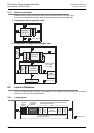
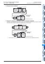
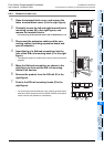
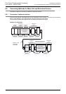
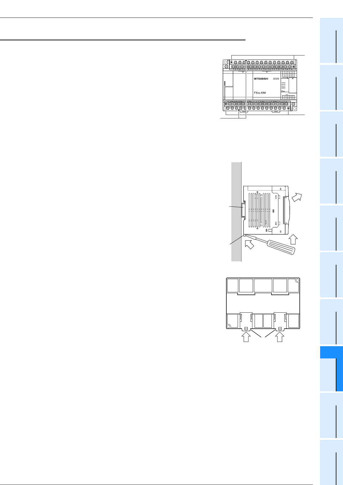
8.4.4 Removal of main unit
1 Open the terminal block cover, and remove the
lower terminal block cover (A in the right figure).
2 Gradually loosen the left and right terminal block
mounting screws (B in the right figure), and
remove the terminal blocks.
→ For anchoring of the terminal block, refer to Subsection 9.1.2.
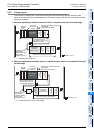
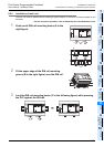
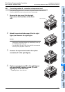
3 Disconnect the extension cables and the con-
necting cables (including expansion board and
special adapters).
4 Insert the tip of a flathead screwdriver into the
hole of the DIN rail mounting hook (C in the right
figure).
• This step also applies for the DIN rail mounting hooks of the special
adapters.
5 Move the flathead screwdriver as shown in the
right figure to draw out the DIN rail mounting
hooks of all devices.
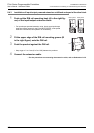
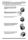
6 Remove the product from the DIN rail (D in the
right figure).
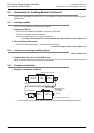
7 Push in the DIN rail mounting hooks (E in the
right figure).
• For input/output powered extension units, 8-point type input/output
extension blocks (except for the FX
2N-8EYR-S-ES/UL) and special
function blocks, this operation is unnecessary.
B
B
A
D
C
4
5
6
7 7
E