


13 Examples of Wiring for Various Uses
189
FX3G Series Programmable Controllers
User's Manual - Hardware Edition
11
High-Speed
Counters
12
Output Wiring
13
Wiring for
Various Uses
14
Test Run,
Maintenance,
Troubleshooting
15
Input/Output
Powered
Extension Units
16
Input/Output
Extension
Blocks
17
Extension
Power Supply
Unit
18
Other Extension
Units and
Options
19
Display Module
20
Terminal Block
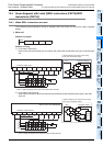
13.2 Digital Switch [DSW Instructions (FNC72)/BIN Instructions (FNC19)]
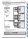
2. Main unit + input/output powered extension unit/block
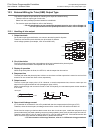
Example of program
Example of wiring
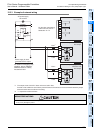
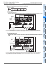
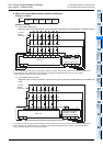
1) In the case of sink wiring
When the main unit and a transistor output (sink) type input/output powered extension unit/block are used
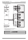
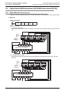
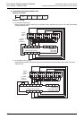
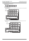
2) In the case of source wiring
When the main unit and a transistor output (source) type input/output powered extension unit/block are
used
M8000
X010 Y030 D100 K1DSW
*1 To use the input terminal (X) of the input/output powered extension unit, wire the terminal as shown by the dotted line.
*2 The terminals in the shaded areas are provided on input/output powered extension units (ex.: FX
2N
-32ET).
Output extension blocks do
not have the terminals.
*1
*2
Digital
switch of
BCD
1248
10
3
10
2
10
1
10
0
X010 X011 X012 X013
24V0V
S/S
Y030 Y031 Y032 Y033
Transistor output (sink)
24+COM
COM1
X
10
3
10
2
10
1
10
0
Input/output powered extension unit
Output extension block
0.1A 50V
diode is
necessary.
Main unit
1248
10
3
10
2
10
1
10
0
0.1A 50V
diode is
necessary.
Digital
switch of
BCD
X010 X011 X012 X013
24V0V
S/S
Y030 Y031 Y032 Y033
0VS/S
+V0
Input/output powered extension unit
Output extension block
Transistor output (source)
Main unit
X
*1
10
3
10
2
10
1
10
0
24V
*1 To use the input terminal (X) of the input/output powered extension unit, wire the terminal as shown by the dotted line.
*2 The terminals in the shaded areas are provided on input/output powered extension units (ex.: FX
2N
-32ET-ESS/UL).
Output extension blocks do not have the terminals.
*2