


12 Output Wiring Procedures
12.1 External Wiring for Relay Output Type
174
FX3G Series Programmable Controllers
User's Manual - Hardware Edition
12.1 External Wiring for Relay Output Type
This section explains relay outputs and external wiring.
For the relay output specifications, refer to the following.
→ For the specifications on the main unit, refer to Subsection 4.4.1.
→ For the specifications on the input/output powered extension unit, refer to Chapter 15.
→ For the specifications on the input/output extension block, refer to Chapter 16.
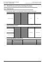
12.1.1 Product life of relay contacts
→ For product life of relay contacts, refer to Subsection 14.4.3.
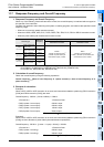
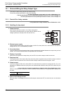
12.1.2 Handling of relay output
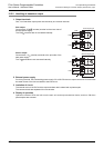
1. Output terminal
One common terminal is used for 4 or 8 relay output points.
The common terminal blocks can drive loads of different circuit
voltage systems (for example,100V AC and 24V DC).
2. External power supply
Use an external power supply of 30V DC or less or 240V AC or less (250V AC or less when the unit does not
comply with CE, UL or cUL standards) for loads.
3. Circuit insulation
The PLC internal circuit and external load circuits are electrically insulated between the output relay coil and
contact. The common terminal blocks are separated from one another.
4. Display of operation
When power is applied to the output relay coil, the LED is lit, and the output contact is turned on.
5. Response time
The response time of the output relay from when the power is applied to the coil until the output contact is
turned on and from when the coil is shut off until the output contact is turned off is approx. 10ms.
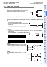
6. Output current
At a circuit voltage of 240V AC or less (250V AC or less when the unit does not comply with CE, UL or cUL
standards), a resistance load of 2A per point or an inductive load of 80VA or less (100V AC or 200V AC) can
be driven.
→ For the life of the contact for switching an inductive load, refer to Subsection 14.4.3.
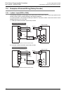
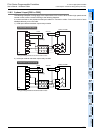
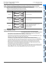
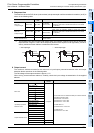
When an inductive load is switched, connect a diode (for commutation) or a surge absorber in parallel with
this load.
7. Open circuit leakage current
Because there is no leakage current even while output contacts are OFF, the neon ball, etc. can be driven
directly.
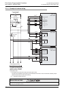
DC circuit Diode (for commutation)
AC circuit Surge absorber
PLC
Load
24V DCFuse
Y 0
Y 1
COM1
Load
100V ACFuse
Y 4
Y 5
COM2