


20 Terminal Block
20.7 FX-16EYR-TB
365
FX3G Series Programmable Controllers
User's Manual - Hardware Edition
11
High-Speed
Counters
12
Output Wiring
13
Wiring for
Various Uses
14
Test Run,
Maintenance,
Troubleshooting
15
Input/Output
Powered
Extension Units
16
Input/Output
Extension
Blocks
17
Extension
Power Supply
Unit
18
Other Extension
Units and
Options
19
Display Module
20
Terminal Block
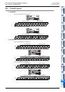
20.7 FX-16EYR-TB
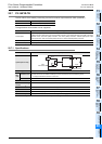
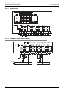
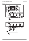
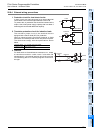
The FX-16EYR-TB is used by connecting it to the FX2N series output extension block (transistor).
The applications shown below are not supported.
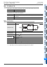
20.7.1 Specifications
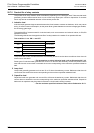
*1. This response time does not include the response delay at the PLC.
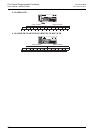
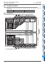
Output Connector
Connectable models FX2N-16EYT-C (sink output)
Unsupported Applications
Pulse outputs
Pulse Y output (PLSY) instruction, acceleration/deceleration setup (PLSR) instruction, pulse width modulation
(PWM) instruction, DOG search zero return (DSZR) instruction, batch data positioning mode (TBL) instruction,
absolute current value read (ABS) instruction, zero return (ZRN) instruction, variable speed pulse output
(PLSV) instruction, drive to increment (DRVI) instruction, drive to absolute (DRVA) instruction
Time division inputs Input matrix (MTR) instruction, digital switch (DSW) instruction
Time division output Seven segment with latch (SEGL) instruction
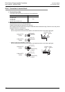
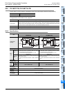
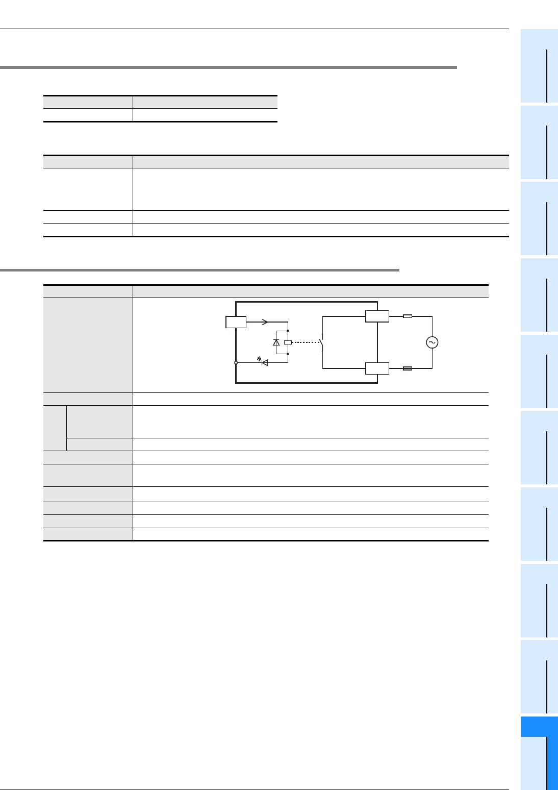
Item Relay output
Input/output circuitry
Load voltage 250V AC or less, 30V DC or less
Max.
load
Resistance load
2A / point
The total load current of resistance loads per common terminal should be the following value.
• 4 output points/common terminal : 8A or less
Inductive load 80 VA
Min. load 5V DC, 2mA Reference value
Open-circuit leakage
current
-
Response time
*1
Approx. 10ms
Circuit isolation Mechanical isolation
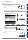
Operation indicators Supplying power to the relay coil will light the LED indicator lamp on panel.
Power consumption 1.92W (80mA 24V DC)
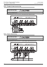
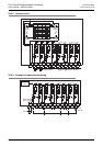
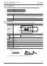
0 to 7
COMn
LED
24V DC
5mA
Fuse
CN1
Connector side
External wiring
24+