


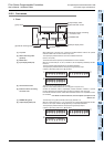

15 Input/Output Powered Extension Units
15.2 Power supply specifications
227
FX3G Series Programmable Controllers
User's Manual - Hardware Edition
11
High-Speed
Counters
12
Output Wiring
13
Wiring for
Various Uses
14
Test Run,
Maintenance,
Troubleshooting
15
Input/Output
Powered
Extension Units
16
Input/Output
Extension
Blocks
17
Extension
Power Supply
Unit
18
Other Extension
Units and
Options
19
Display Module
20
Terminal Block
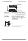
15.2.2 Part names
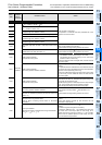
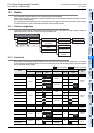
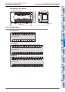
1. Front
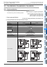
[1] Top cover When adding this to the main unit, connect the supplied extension cable or the optional
extension cable to the connector under this top cover.
[2] DIN rail mounting hooks
(2 places)
The input/output powered extension unit can be installed on DIN rail
(35mm (1.38") wide).
[3] Model name The model name of the input/output powered extension unit is indicated.
[4] Input display LEDs (red) When an input terminal (X0, X1, etc.) is turned on, the corresponding LED lamps are also
turned on.
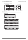
The input numbers change depending on input/output allocation.
The input/output powered extension unit (48 points type) assigns input
numbers in ascending order from A B C below.
[5] Terminal block covers
The covers can be opened about 90 for wiring.
Keep the covers closed while the PLC is running (the unit power is on).
[6] Extension device connecting
connector cover
Connect the extension cable of input/output powered extension unit/block or special
function unit/block to the extension device connecting connector under this cover.
FX
3U Series extension devices, FX2N Series extension devices, are compatible and can
be connected.
→ For details on extension devices, refer to Chapter 15, Chapter 16 and
Section 18.1.
[7] POWER LED (green) The LED lamp is on (green) while the power supply terminal is on.
[8] Output display LEDs (red) When an output terminal (Y0, Y1, etc.) is turned on, the corresponding LED lamps are also
turned on. The output numbers change depending on input/output allocation.
The input/output powered extension unit (48 points type) assigns output
numbers in ascending order from A B C below.
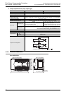
[1] Top cover
[2] DIN rail mounting hooks
[3] Model name
[8] Output display LEDs
[7] POWER LED
[6] Extension device connecting
connector cover
[5] Terminal block covers
[4] Input display LEDs
A
0 1 2 3 4 5 6 7 0 1 2 3 4 5 6 7
C
B
0 1 2 3 4 5 6 7
A
0 1 2 3 4 5 6 7 0 1 2 3 4 5 6 7
C
B
0 1 2 3 4 5 6 7