


8 Installation In Enclosure
8.6 Connecting Methods for Main Unit and Extension Devices
115
FX3G Series Programmable Controllers
User's Manual - Hardware Edition
1
Introduction
2
Features and
Part Names
3
Product
Introduction
4
Specifications
5
Version and
Peripheral
Devices
6
System
Configuration
7
Input/Output
Nos., Unit Nos.
8
Installation
9
Preparation and
Power Supply
Wiring
10
Input Wiring
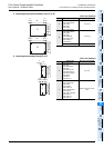
8.6.2 Connecting method A - connection of expansion board
This subsection explains how to connect the expansion board to the main unit.
The FX
3G-40MT/ES is used as the main unit in this example.
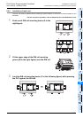
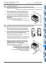
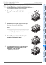
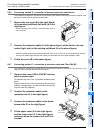
1 Remove the top cover (A in the right
figure) from the front face of the main
unit.
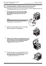
2 Attach the provided side cover (B in the right
figure) as shown in the right figure.
Caution
- Attachment of the side cover is not necessary when
connecting the expansion board only under the top cover (S)
of a 40/60-point type main unit.
-FX
3G-4EX-BD, FX3G-2EYT-BD, FX3G-8AV-BD cannot attach
in the top cover (S) side of a main unit.
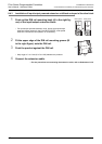
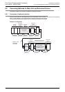
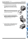
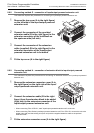
3 Connect the expansion board to the option
connector (C in the right figure).
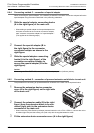
4 Fix the expansion board (E in the right figure)
with provided M3 tapping screws (D in the
right figure) to the main unit.
• Tightening torque : 0.3 to 0.6 N•m
A
1
Top cover (S)
B
C
3
D
E