363
FX3S/FX3G/FX3GC/FX3U/FX3UC Series
Programming Manual - Basic & Applied Instruction Edition
13 High-Speed Processing – FNC 50 to FNC 59
13.6 FNC 55 – HSZ / High-Speed Counter Zone Compare
11
FNC30-FNC39
Rotation and
Shift
12
FNC40-FNC49
Data Operation
13
FNC50-FNC59
High-Speed
Processing
14
FMC60-FNC69
Handy
Instruction
15
FNC70-FNC79
External FX I/O
Device
16
FNC80-FNC89
External FX
Device
17
FNC100-FNC109
Data
Transfer 2
18
FNC110-FNC139
Floating Point
19
FNC140-FNC149
Data
Operation 2
20
FNC150-FNC159
Positioning
Control
13.6.1 Program in which comparison result is set to ON when power is turned ON
[ZCP (FNC 11) instruction]
DHSZ instruction outputs the comparison result only when a counting pulse is input. Even if the current value of C235
is "0", Y010 remains OFF at the time of startup.
For initializing Y010, compare the current value of C235 with K1000 and K1200 and drive Y010 by DZCPP instruction
(for general zone comparison) as pulse operation only at the time of startup.
Refer to the program example shown below.
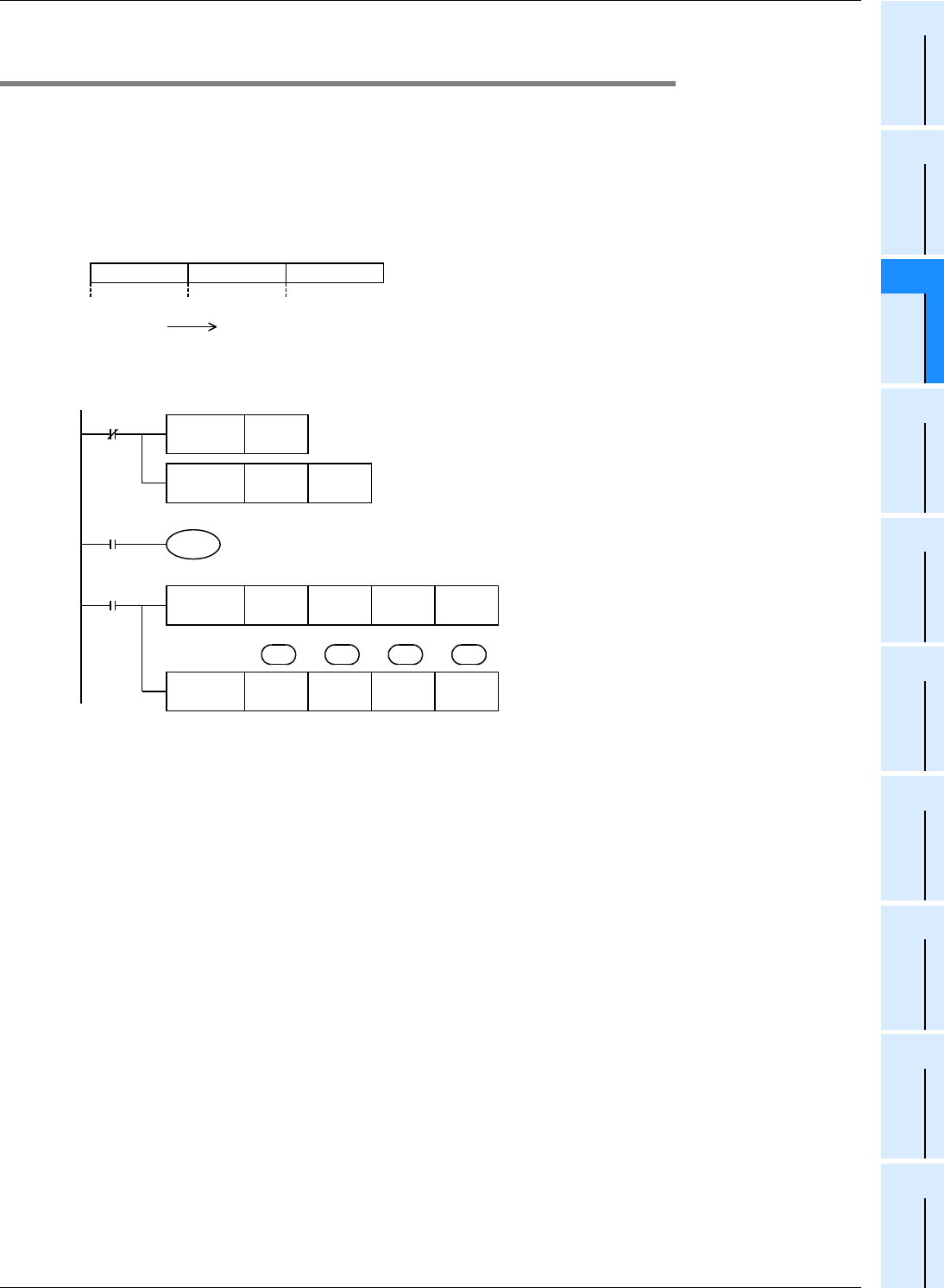
Explanation of operation
The outputs Y010 to Y012 are as shown below:
Program example
Y010 = ON Y011 = ON Y012 = ON
1000 1200
Current value of C235
0
X010
RST C235
C235
M8000
RUN monitor
X010
FNC 11
DZCPP
K1000 K1200 C235 Y010
K9999
…
pulse input: X000
FNC 55
DHSZ
K1000 K1200 C235 Y010
Start
FNC 40
ZRST
Y010 Y012
Y010 to Y012 are reset.
Immediately after start, comparison is
executed only once.
K1000
>
C235 :Y010 ON
K1000
≤
C235
≤
K1200 :Y011 ON
K1200
<
C235 :Y012 ON
After start, comparison is executed
when each pulse is input from X000.
K1000
>
C235 :Y010 ON
K1000
≤
C235
≤
K1200 :Y011 ON
K1200
<
C235 :Y012 ON
S
1
D
S
2
S


