21 Memory Cassette
375
FX3G Series Programmable Controllers
User's Manual - Hardware Edition
21
Memory
Cassette
22
Battery
A
Special Devices
(M8000-,D8000-)
B
Instruction List
C
Discontinued
models
D
Precautions for
battery
transportation
E
Handling of
batteries in EU
member states
21.1 Outline
21. Memory Cassette
21.1 Outline
The memory cassette can be installed at the main unit, and when installed, the memory cassette's internal
program is used in place of the internal EEPROM memory. The loader function transfers (reads and writes)
programs between the memory cassette and the internal EEPROM.
21.2 Specifications
21.2.1 Electrical specifications
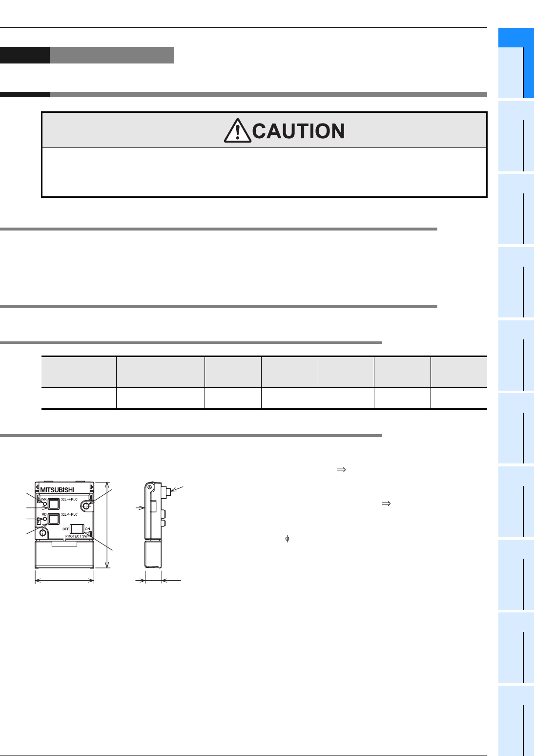
21.2.2 Part names and External dimensions
FX3G-EEPROM-32L
[1]RD key
(Reading: PLC memory cassette)
[2]RD LED
[3]WR key
(writing: memory cassette PLC)
[4]WR LED
[5]Memory cassette fixing holes
(2- 3.2 Mounting holes)
[6]PROTECT switch
[7]Detachment lever
[8]Main unit connector
STARTUP AND MAINTENANCE
PRECAUTIONS
• Turn off the power to the PLC before attaching or detaching the memory cassette. If the memory cassette is attached or detached
while the PLC's power is on, the data in the memory may be destroyed, or the memory cassette may be damaged.
• Do not disassemble or modify the PLC.
Doing so may cause fire, equipment failures, or malfunctions.
For repair, contact your local Mitsubishi Electric representative.
Model Name Max. Memory Capacity Memory Type
Max.
Allowable
Write
PROTECT
Switch
Loader
Function
Compatible
Versions
FX3G-EEPROM-32L
32000 steps
(2k/4k/8k/16k selectable)
EEPROM
memory
10,000 times Provided Provided
1st article
(Ver.1.00)
Units: mm (inches)
51.2(2.02")
35(1.38")
9.6(0.38")
[4]
[3]
[2]
[1]
[5]
[7]
[8]
[6]


