388
FX3S/FX3G/FX3GC/FX3U/FX3UC Series
Programming Manual - Basic & Applied Instruction Edition
14 Handy Instruction – FNC 60 to FNC 69
14. Handy Instruction – FNC 60 to FNC 69
FNC 60 to FNC 69 provide handy instructions which achieve complicated control in a minimum sequence program.
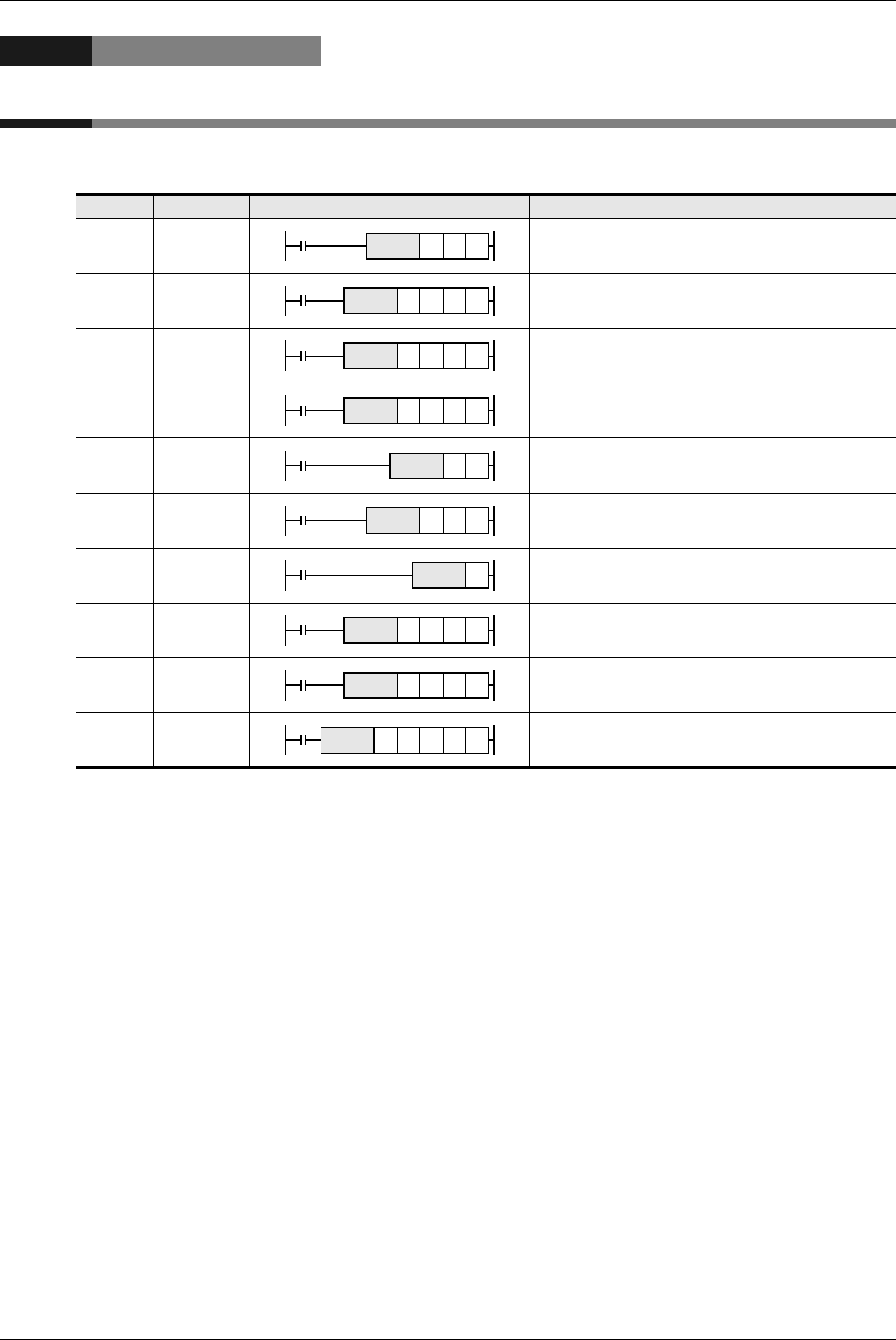
FNC No. Mnemonic Symbol Function Reference
60 IST Initial State Section 14.1
61 SER Search a Data Stack Section 14.2
62 ABSD Absolute drum sequencer Section 14.3
63 INCD Incremental drum sequencer Section 14.4
64 TTMR Teaching Timer Section 14.5
65 STMR Special Timer Section 14.6
66 ALT Alternate State Section 14.7
67 RAMP Ramp Variable Value Section 14.8
68 ROTC Rotary Table Control Section 14.9
69 SORT SORT Tabulated Data
Section
14.10
IST D1 D2S
nSER DS2S1
nABSD DS2S1
nINCD DS2S1
nDTTMR
STMR m DS
DALT
n
RAMP
DS2S1
DROTC m2m1S
nSORT Dm2m1S


