


15 Input/Output Powered Extension Units
15.8 FX2N-48ER-UA1/UL
243
FX3G Series Programmable Controllers
User's Manual - Hardware Edition
11
High-Speed
Counters
12
Output Wiring
13
Wiring for
Various Uses
14
Test Run,
Maintenance,
Troubleshooting
15
Input/Output
Powered
Extension Units
16
Input/Output
Extension
Blocks
17
Extension
Power Supply
Unit
18
Other Extension
Units and
Options
19
Display Module
20
Terminal Block
15.8 FX2N-48ER-UA1/UL
15.8.1 Product specifications
The generic specifications are the same as those for the main unit.
→ Refer to Section 4.1 for generic specifications.
For external wiring, refer to the following chapters.
→ Refer to Chapter 9 for power supply wiring.
→ Refer to Chapter 10 for input wiring.
→ Refer to Chapter 12 for output wiring.
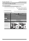
1. Power supply specifications
→ For the power supply specifications, refer to Section 15.2.
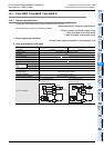
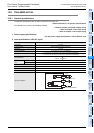
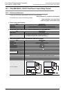
2. Input specifications (100V AC Input)
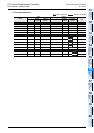
Item FX2N-48ER-UA1/UL
Input points 24 points
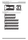
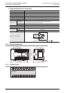
Connection type Removable terminal block (M3 screw)
Input form AC input
Input signal voltage 100 to 120V AC +10%,-15% 50/60 Hz
Input signal current
4.7 mA/100V AC 50 Hz (70% or less when turned on simultaneously)
6.2 mA/110V AC 60 Hz (70% or less when turned on simultaneously)
Input impedance
Approx. 21 k /50 Hz
Approx. 18 k /60 Hz
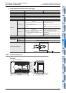
Input response
time
Input ON current 3.8mA or more/80V AC
Input OFF current 1.7mA or less/30V AC
Input response time Approx. 25 to 30ms
Input signal form Contact input
Input circuit insulation Photo-coupler insulation
Indication of input operation LED on panel lights when input.
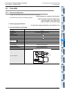
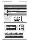
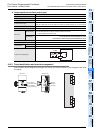
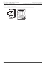
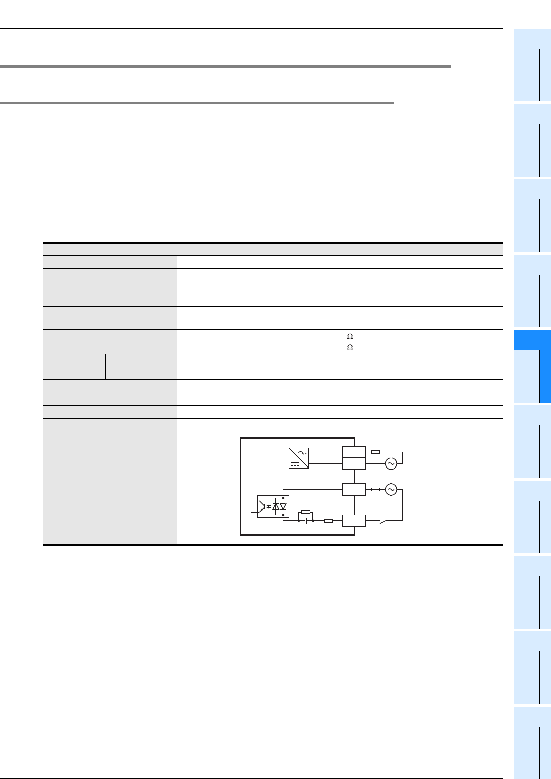
Input circuit diagram
N
L
100 to 240V AC
Fuse
X
COM
*1
*1 Input impedance