


13 Examples of Wiring for Various Uses
195
FX3G Series Programmable Controllers
User's Manual - Hardware Edition
11
High-Speed
Counters
12
Output Wiring
13
Wiring for
Various Uses
14
Test Run,
Maintenance,
Troubleshooting
15
Input/Output
Powered
Extension Units
16
Input/Output
Extension
Blocks
17
Extension
Power Supply
Unit
18
Other Extension
Units and
Options
19
Display Module
20
Terminal Block
13.4 Seven Segment with Latch [SEGL Instructions (FNC74)/BCD Instructions (FNC18)]
13.4 Seven Segment with Latch [SEGL Instructions (FNC74)/BCD
Instructions (FNC18)]
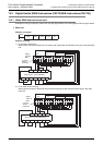
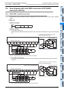
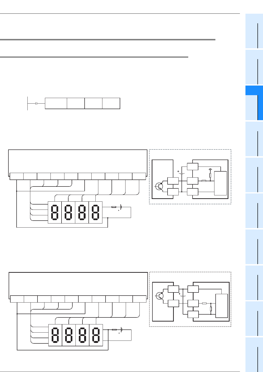
13.4.1 When SEGL instructions are used
This subsection gives examples of wiring for displaying the current value of D100 on the 4-digit 7-segment
display.
1. Main unit
Example of program
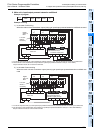
Example of wiring
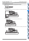
1) In the case of sink wiring
When inputs are used for both sink and source and outputs are the transistor sink type in the used main
unit
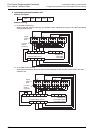
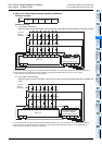
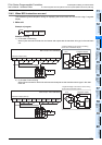
2) In the case of source wiring
When inputs are used for both sink and source and outputs are the transistor source type in the used
main unit
M8000
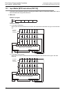
D100 Y010 K1SEGL
* Use a 7-segment display with a latch and a built-in BCD decoder.
10
3
10
2
10
1
10
0
124
8
10
3
10
2
10
1
10
0
1
2
4
Y011Y010 Y012 Y013 COM5 Y014 Y015 Y016 Y017
8
COM4
Transistor output (sink)
*
Main unit (Ex: FX
3G
-40MT/ES)
Signal
-
Internal
circuit
7-segment display
+
Y
COM1
PLC
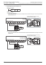
7-segment display to be used for sink wiring
(in the case of transistor output)
Signal
-
7-segment display
+
Y
PLC
7-segment display to be used for source wiring
(in the case of transistor output)
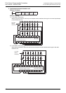
+V0
10
3
10
2
10
1
10
0
124
8
10
3
10
2
10
1
10
0
1
2
4
Y011Y010 Y012 Y013 +V5 Y014 Y015 Y016 Y017
8
Transistor output (source)
*
* Use a 7-segment display with a latch and a built-in BCD decoder.
Main unit (Ex: FX
3G-40MT/ESS)
+V4
Internal
circuit