


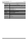
2 Features and Part Names
2.2 Names and Functions of Parts
32
FX3G Series Programmable Controllers
User's Manual - Hardware Edition
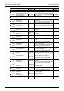
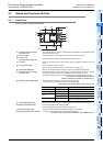
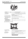
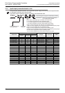
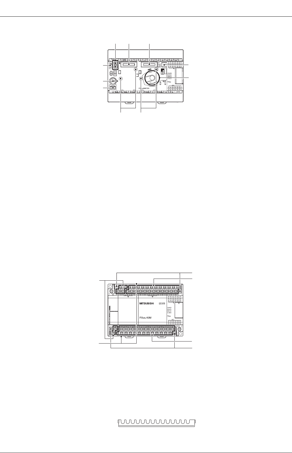
When the top covers are open
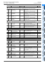
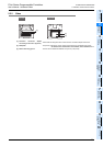
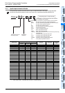
When the terminal block covers are open
[9][10]
[8]
[7]
[6][5][4]
[2]
[3]
[1]
[1] Peripheral device connecting
connector (USB)
Connect a programming tool (PC) to program a sequence.
→ For details on applicable peripheral devices, refer to Chapter 5.
[2] Peripheral device connecting
connector (RS-422)
Connect a programming tool to program a sequence.
→ For details on applicable peripheral devices, refer to Chapter 5.
[3] RUN/STOP switch To stop writing (batch) of the sequence program or operation, set the switch to STOP
(slide it downward).
To start operation (run the machine), set it to RUN (slide it upward).
[4] Variable analog potentiometers Two variable analog potentiometers are built in.
Upper side : VR1, Lower side : VR2
[5] Optional equipment connector1 Connect the expansion board and memory cassette to the connector.
[6] Optional equipment connector2
(40 points, 60 points type only)
Connect the expansion board, display module and memory cassette to the connector.
[7] Battery connector Connect the optional battery to the connector.
[8] Battery holder This holder accommodates the optional battery.
[9] Optional equipment connecting
screw holes2 (2 places)
(40 points, 60 points type only)
These holes are designed to secure the expansion board and memory cassette with
screws.
[10] Optional equipment connecting
screw holes1 (2 places)
These holes are designed to secure the expansion board and memory cassette with
screws.
[1] Power supply terminal Connect the power supply to the main unit.
[2] Terminal block mounting
screws
If the main unit must be replaced, loosen the screws (slightly loosen the left and right
screws), and the upper part of the terminal block can be removed.
→ For anchoring of the terminal block, refer to Subsection 9.1.2.
[3] Input (X) terminals Wire switches and sensors to the terminals.
[4] Output (Y) terminals Wire loads (contactors, solenoid valves, etc.) to be driven to the terminals.
[5] Terminal cover A protective terminal cover (refer to the following drawing) is fitted to the lower stage of
each terminal block.
The cover prevents fingers from touching terminals, thereby improving safety.
[3]
[4]
[2]
[5]
[1]
[2]