


10 Input Wiring Procedures
10.3 100V AC Input
153
FX3G Series Programmable Controllers
User's Manual - Hardware Edition
1
Introduction
2
Features and
Part Names
3
Product
Introduction
4
Specifications
5
Version and
Peripheral
Devices
6
System
Configuration
7
Input/Output
Nos., Unit Nos.
8
Installation
9
Preparation and
Power Supply
Wiring
10
Input Wiring
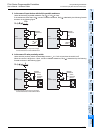
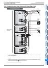
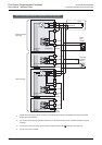
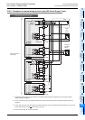
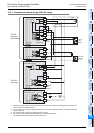
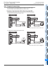
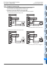
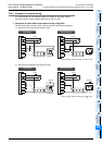
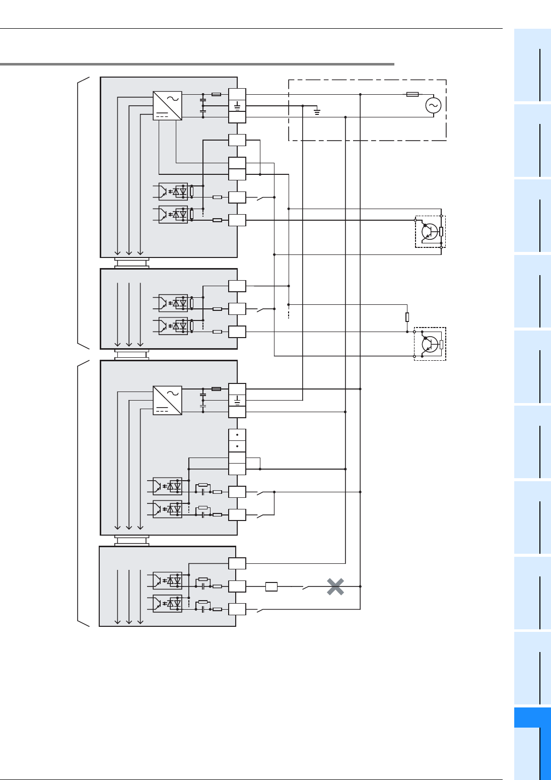
10.3.3 Examples of external wiring (100V AC input)
*1 Handle the power supply circuit correctly in accordance with Chapter 9 "Preparation for Wiring and
Power Supply Wiring Procedures."
*2 For an input device having a parallel resistance or a two-wire proximity switch, a bleeder resistance
may be required
*3 Do not take input signals from loads generating surge.
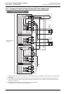
24V DC
input type
(Sink wiring)
X000
S/S
0V
24V
Main unit
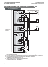
N
L
X001
X0
S/S
X1
Input extension block
X0
Input / output powered extension unit
FX2N-48ER-UA1/UL
N
L
X1
5V 0V 24V
Fuse
Class D
grounding
Input
impedance
Input
terminal
Input
terminal
Input
terminal
*1
*2
24V
0V
Two-wire
proximity
sensor
COM
COM
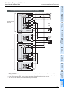
100V AC
input type
Three-
wire
sensor
X0
COM
X1
Input extension block
MC
*3
*4
The "24V" and "0V" terminals are located on the output terminal side.
For details on the terminal layout, refer to Section 4.7.
*4
*4
5V 0V 24V
5V 0V 24V
5V 0V 24V
FX2N-8EX-UA1/UL