


15 Input/Output Powered Extension Units
15.6 FX2N-32ET, FX2N-48ET, FX2N-48ET-D
239
FX3G Series Programmable Controllers
User's Manual - Hardware Edition
11
High-Speed
Counters
12
Output Wiring
13
Wiring for
Various Uses
14
Test Run,
Maintenance,
Troubleshooting
15
Input/Output
Powered
Extension Units
16
Input/Output
Extension
Blocks
17
Extension
Power Supply
Unit
18
Other Extension
Units and
Options
19
Display Module
20
Terminal Block
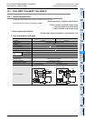
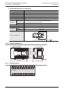
3. Output specifications (transistor output type)
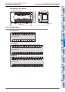
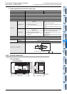
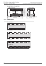
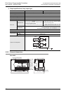
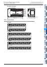
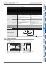
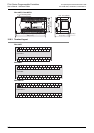
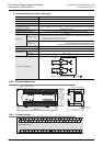
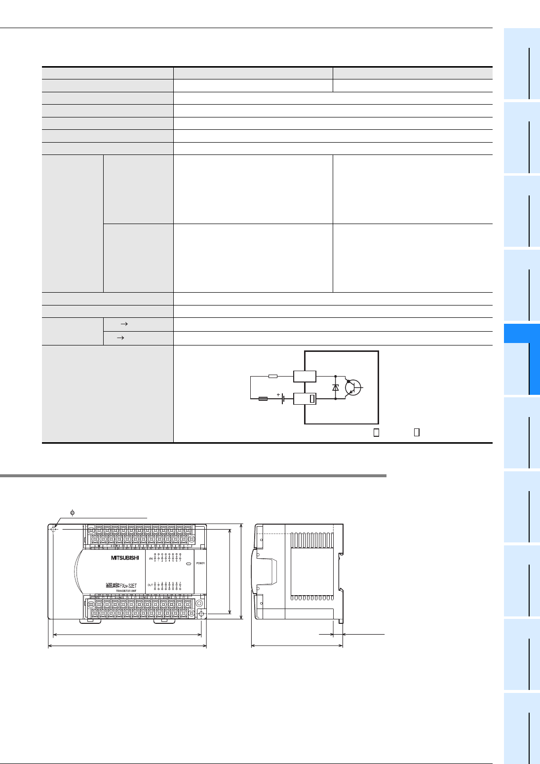
15.6.2 External dimensions
FX2N-32ET
Item FX2N-32ET FX2N-48ET, FX2N-48ET-D
Output Points 16 points 24 points
Connection type Removable terminal block (M3 screw)
Output unit/type Transistor/sink output
External power supply 5 to 30V DC
Output circuit insulation Photo-coupler insulation
Indication of output operation Activation of the photo-coupler will light the LED indicator lamp on panel.
Max. load
Resistance load
0.5A/point
The total load current per common terminal
should be the following value.
• 4 output points/common terminal: 0.8A or
less
0.5A/point
The total load current per common terminal
should be the following value.
• 4 output points/common terminal: 0.8A or
less
• 8 output points/common terminal: 1.6A or
less
Inductive load
12W/24V DC
The total of inductive loads per common
terminal should be the following value.
• 4 output point/common terminal: 19.2W or
less/24V DC
12W/24V DC
The total of inductive loads per common
terminal should be the following value.
• 4 output point/common terminal: 19.2W or
less/24V DC
• 8 output points/common terminal: 38.4W or
less/24V DC
Open circuit leakage current 0.1mA/30V DC
Min. load -
Response time
OFF ON
0.2ms or less/200mA (at 24V DC)
ON OFF
0.2ms or less/200mA (at 24V DC)
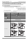
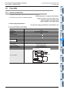
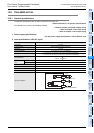
Output circuit configuration
Load
Fuse
DC power
supply
Y
COM
A common number applies to the of [COM ].
150 (5.91")
140 (5.52") (mounting hole pitch)
80 (3.15")
(mounting hole pitch)
90 (3.55")
9 (0.36")
Unit : mm (inches)
87 (3.43")
2-
4.5 mounting holes