148
FX3S/FX3G/FX3GC/FX3U/FX3UC Series
Programming Manual - Basic & Applied Instruction Edition
4 Devices in Detail
4.11 Index Register [V and Z]
4.11 Index Register [V and Z]
Index registers can be used in the same way as of data registers. But they are special registers since they can change
the contents of device numbers and numeric values by program when combined with another device number or
numeric value in operands of applied instructions.
4.11.1 Numbers of index registers
The table below shows numbers of index registers (V and Z). (Numbers are assigned in decimal.)
When only "V" or "Z" is specified, it is handled as "V0" or "Z0" respectively.
*1. The characteristics related to protection against power failure cannot be changed by parameters.
4.11.2 Functions and structures
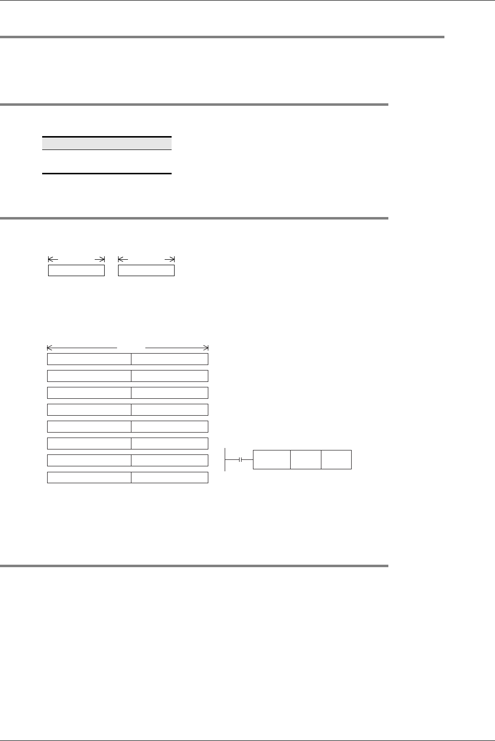
1. 16-bit type
Index registers have the same structures as data registers.
2. 32-bit type
Make sure to use Z0 to Z7 when indexing a device in a 32-bit applied instruction or handling a numeric value outside
the 16-bit range.
4.11.3 Indexing of devices
Available devices and the contents of indexing are as described below:
→ For indexing method and cautions, refer to Section 5.7.
Decimal devices/numeric values: M, S, T, C, D, R, KnM, KnS, P and K
For example, when "V0 = K5" is specified and "D20V0" is executed, an instruction is executed for the device number
D25 (D20 + 5).
Constants can be indexed also. When "K30V0" is specified, an instruction is executed for decimal value K35 (30 + 5).
Octal devices: X, Y, KnX and KnY
For example, when "Z1 = K8" is specified and "X0Z1" is executed, an instruction is executed for the device number
X10 (X0 + 8: addition of octal value). When indexing for a device whose device number is handled in octal, a numeric
value converted into octal is added for the contents of V and Z.
Accordingly, note that when "Z1 = K10" is specified "X0Z1" indicates that X12 is specified, and X10 is not specified.
Hexadecimal numeric values: H
For example, when "V5 = K30" is specified and a constant "H30V5" is specified, it is handled as H4E (30H + K30).
When "V5 = H30" is specified and a constant "H30V5" is specified, it is handled as H60 (30H + 30H).
Index type
V0 (V) to V7, Z0 (Z) to Z7
16 points
*1
V
16 bits
Z
16 bits
V0 to V7:
8 points
Z0 to Z7:
8 points
V0 (high-order side) Z0 (low-order side)
V1 (high-order side) Z1 (low-order side)
V2 (high-order side) Z2 (low-order side)
V3 (high-order side) Z3 (low-order side)
V4 (high-order side) Z4 (low-order side)
V5 (high-order side) Z5 (low-order side)
V6 (high-order side) Z6 (low-order side)
32 bits
V7 (high-order side) Z7 (low-order side)
This is because FX PLCs handle Z as the low-order side of a 32-bit
register as shown in combinations of V and Z in the figure on the left.
Even if V0 to V7 on the high-order side is specified, indexing is not
executed.
When index registers are specified as a 32-bit device, both V (high-
order side) and Z (low-order side) are referred to at the same time.
If a numeric value for another purpose remains in V (high-order side),
consequently the numeric value here becomes extremely large, thus
an operation error occurs.
Example of writing to 32-bit index registers
FNC 12
DMOV
K300 Z2
K300→(V2,Z2)
Even if an index value in a 32-bit applied instruction does not exceed
the 16-bit numeric range, use a 32-bit operation instruction such as
DMOV for writing a numeric value to Z as shown in the above figure
so that both V (high-order side) and Z (low-order side) are overwritten
at the same time.


